Definition of parallel lines. Parallel are two straight lines that lie in the same plane and do not intersect throughout their entire length.
Straight lines AB and CD (Fig. 57) will be parallel. The fact that they are parallel is sometimes expressed in writing: AB || CD.
Theorem 34. Two lines perpendicular to the same third are parallel.
Given straight lines CD and EF perpendicular to AB (Fig. 58)
CD ⊥ AB and EF ⊥ AB.
It is required to prove that CD || EF.

Proof. If the lines CD and EF were not parallel, they would intersect at some point M. In this case, two perpendiculars would be dropped from the point M to the line AB, which is impossible (Theorem 11), hence the line CD || EF (CHTD).
Theorem 35. Two lines, one of which is perpendicular and the other oblique to a third, always intersect.
Given two lines EF and CG, of which EF ⊥ AB and CG is oblique to AB (Fig. 59).
It is required to prove that CG will meet the line EF or that CG is not parallel to EF.

Proof. From point C we restore perpendicular CD to line AB, then at point C an angle DCG is formed, which we will repeat so many times that line CK falls below line AB. Suppose that for this we repeat the angle DCG n times, as
In a similar way, we plot the line CE on the line AB also n times, so that CN = nCE.
From points C, E, L, M, N, we construct perpendiculars LL", MM", NN". The space contained between two parallel segments CD, NN" and segment CN will be n times greater than the space contained between two perpendiculars CD, EF and segment CE, so DCNN" = nDCEF.
The space enclosed by the angle DCK contains the space DCNN", therefore,
DCK > CDNN" or
nDCG > nDCEF, whence
DCG > DCEF.
The last inequality can take place only when the line CG leaves the DCEF space during its continuation, i.e. when the line CG meets the line EF, hence the line CG is not parallel to CF (PTD).
Theorem 36. A line perpendicular to one of the parallels is also perpendicular to the other.
Given two parallel lines AB and CD and a line EF perpendicular to CD (Fig. 60).
AB || CD, EF ⊥ CD
It is required to prove that EF ⊥ AB.

Proof. If line AB were oblique to EF, then two lines CD and AB would intersect, because CD ⊥ EF and AB is oblique to EF (Theorem 35), and lines AB and CD would not be parallel, which would contradict this condition, therefore, the line EF is perpendicular to CD (PTD).
Angles formed by the intersection of two lines by a third line. At the intersection of two lines AB and CD by the third line EF (Fig. 61), eight angles α, β, γ, δ, λ, μ, ν, ρ are formed. These corners receive special names.

The four angles α, β, ν and ρ are called external.
The four angles γ, δ, λ, μ are called internal.
The four angles β, γ, μ, ν and the four angles α, δ, λ, ρ are called unilateral, because they lie on one side of the line EF.
In addition, the angles, when taken in pairs, receive the following names:
The angles β and μ are called relevant . In addition to this pair, the same corresponding angles will be pairs of angles:γ and ν, α and λ, δ and ρ.
The pairs of angles δ and μ, as well as γ and λ are called internal cross-lying .
Pairs of angles β and ρ, as well as α and ν are called external cross-lying .
Pairs of angles γ and μ, as well as δ and λ are called internal unilateral .
Pairs of angles β and ν, as well as α and ρ are called external unilateral .
Conditions for two lines to be parallel
Theorem 37. Two straight lines are parallel if at the intersection of their third they have equal: 1) corresponding angles, 2) internal cross-lying, 3) external cross-lying, and, finally, if 4) the sum of internal one-sided equals two straight lines, 5) the sum of external unilateral is equal to two straight lines.
Let us prove each of these parts of the theorem separately.
1st case. The corresponding angles are(Fig. 62).
Given. The angles β and μ are equal.
Proof. If the lines AB and CD intersected at the point Q, then the triangle GQH would be obtained, in which the external angle β would be equal to the internal angle μ, which would contradict Theorem 22, therefore, the lines AB and CD do not intersect or AB || CD (ChTD).

2nd case. Internal cross-lying angles are equal, that is, δ = μ.
Proof. δ = β as vertical, δ = μ by assumption, hence β = μ. That is, the corresponding angles are equal, and in this case the lines are parallel (1st case).
3rd case. External cross-lying angles are equal, that is, β = ρ.
Proof. β = ρ by condition, μ = ρ as vertical, hence β = μ, since the corresponding angles are equal. This implies that AB || CD (1st case).
4th case. The sum of internal one-sided is equal to two straight lines or γ + μ = 2d.
Proof. β + γ = 2d as a sum of adjacent ones, γ + μ = 2d by assumption. Therefore, β + γ = γ + μ, whence β = μ. The corresponding angles are equal, therefore, AB || CD.
5th case. The sum of outer one-sided is equal to two straight lines, that is, β + ν = 2d.
Proof. μ + ν = 2d as a sum of adjacent ones, β + ν = 2d by assumption. Therefore, μ + ν = β + ν, whence μ = β. The corresponding angles are equal, therefore, AB || CD.
Thus, in all cases AB || CD (ChTD).
Theorem 38(reverse 37). If two lines are parallel, then at the intersection of their third line will be equal: 1) internal cross-lying angles, 2) external cross-lying, 3) the corresponding angles and are equal to two straight lines 4) the sum of internal one-sided and 5) the sum of external one-sided angles.
Given two parallel lines AB and CD, that is, AB || CD (Fig. 63).
It is required to prove that all the above conditions are satisfied.
1st case. Let us intersect two parallel lines AB and CD by a third oblique line EF. Denote by G and H the intersection points of lines AB and CD of line EF. From point O of the midpoint of line GH we drop a perpendicular to line CD and continue it until it intersects line AB at point P. Line OQ perpendicular to CD is also perpendicular to AB (Theorem 36). Right triangles OPG and OHQ are equal, because OG = OH by construction, ∠ HOQ= ∠ POG as vertical angles, hence OP = OQ.

It follows from this that δ = μ, i.e., internal cross-lying angles are equal.
2nd case. If AB || CD, then δ = μ, and since δ = β and μ = ρ, then β = ρ, i.e. external cross-lying angles are equal.
3rd case. If AB || CD, then δ = μ, and since δ = β, then β = μ, therefore, corresponding angles are equal.
4th case. If AB || CD, then δ = μ, and since δ + γ = 2d, then μ + γ = 2d, i.e. the sum of internal one-sided equals two straight lines.
5th case. If AB || CD, then δ = μ.
Since μ + ν = 2d, μ = δ = β, hence ν + β = 2d, i.e. the sum of the outer one-sided equals two straight lines.
From these theorems follows consequence. Through a point, only one line can be drawn parallel to another line.
Theorem 39. Two lines parallel to a third are parallel to each other.
Given three lines (Fig. 64) AB, CD and EF, of which AB || EF, CD || EF.
It is required to prove that AB || CD.

Proof. Let us intersect these lines with the fourth line GH.
If AB || EF, then ∠ α = ∠ γ as appropriate. If CD || EF, then ∠ β = ∠ γ as well as the corresponding ones. Consequently, ∠ α = ∠ β .
If the corresponding angles are equal, then the lines are parallel, therefore, AB || CD (ChTD).
Theorem 40. Same-named angles with parallel sides are equal.
Given the same name (both acute or both obtuse) angles ABC and DEF, their sides are parallel, i.e. AB || DE, BC || EF (Fig. 65).
It is required to prove that ∠ B= ∠ E.

Proof. We continue side DE until it intersects line BC at point G, then
∠ E = ∠ G as corresponding from the intersection of sides parallel to BC and EF of the third line DG.
∠ B = ∠ G as corresponding to the intersection of parallel sides AB and DG of line BC, hence
∠ E = ∠ B (RTD).
Theorem 41. Opposite angles with parallel sides complement each other to two straight lines.
Given two opposite angles ABC and DEF (Fig. 66) with parallel sides, therefore, AB || DE and BC || EF.
It is required to prove that ABC + DEF = 2d.

Proof. We continue line DE until it intersects line BC at point G.
∠B+ ∠ DGB = 2d as the sum of the interior one-sided angles formed by the intersection of parallel AB and DG of the third line BC.
∠ DGB = ∠ DEF as corresponding, therefore,
∠B+ ∠ DEF = 2d (PTD).
Theorem 42. Like angles with perpendicular sides are equal and opposite angles complement each other to two straight lines.
Consider two cases: when A) the angles are of the same name and when B) they are opposite.
1st case. The sides of two identical angles DEF and ABC (Fig. 67) are perpendicular, i.e. DE ⊥ AB, EF ⊥ BC.
It is required to prove that ∠ DEF = ∠ ABC.

Proof. Draw lines BM and BN from point B parallel to lines DE and EF so that
BM || DE, BN || EF.
These lines are also perpendicular to the sides of the given angle ABC, i.e.
BM ⊥ AB and BN ⊥ BC.
Because ∠ NBC = d, ∠ MBA = d, then
∠NBC= ∠MBA(a)
Subtracting from both sides of equality (a) for the NBA angle, we find
∠ MBN=∠ABC
Since the angles MBN and DEF are of the same name and with parallel sides, they are equal (Theorem 40).
∠ MBN = ∠DEF(b)
Equations (a) and (b) imply the equality
∠ ABC = ∠ DEF (phd).
2nd case. Angles GED and ABC with perpendicular sides are opposite.
It is required to prove that ∠ GED + ∠ ABC = 2d (Fig. 67).
Proof. The sum of the angles GED and DEF is equal to two right angles.
GED + DEF = 2d
DEF = ABC, so
GED + ABC = 2d (pthd).
Theorem 43. Parts of parallel lines between other parallel lines are equal.
Given four lines AB, BD, CD, AC (Fig. 68), of which AB || CD and BD || AC.
It is required to prove that AB = CD and BD = AC.

Proof. Connecting point C with point B by segment BC, we get two equal triangles ABC and BCD, because
BC - common side,
∠ α = ∠ β (as interior cross-lying from the intersection of parallel lines AB and CD of the third line BC),
∠ γ = ∠ δ (as inner cross-lying lines from the intersection of parallel lines BD and AC of line BC).
Thus, triangles have an equal side and two equal angles lying on it.
Opposite equal angles α and β are equal sides AC and BD, and opposite equal angles γ and δ are equal sides AB and CD, therefore,
AC = BD, AB = CD (PTD).
Theorem 44. Parallel lines are equidistant from each other along their entire length.
The distance of a point from a line is determined by the length of the perpendicular dropped from the point to the line. To determine the distance of any two points A and B parallel to AB from CD, we drop the perpendiculars AC and BD from points A and B.
Given a line AB parallel to CD, line segments AC and BD are perpendicular to line CD, i.e. AB || CD, AC ⊥ DC, BD ⊥ CD (Fig. 69).
It is required to prove that AC = BD.

Proof. The lines AC and BD, being both perpendicular to CD, are parallel, and therefore, AC and BD, as parts of the parallels between the parallel ones, are equal, i.e., AC = BD (phd).
Theorem 45(reverse 43). If the opposite parts of four intersecting lines are equal, then these parts are parallel.
Four intersecting straight lines are given, the opposite parts of which are equal: AB = CD and BD = AC (Fig. 68).
It is required to prove that AB || CD and BD || AC.
Proof. Connect points B and C with line BC. Triangles ABC and BDC are equal because
BC - common side,
AB = CD and BD = AC by convention.
From here
∠ α = ∠ β , ∠ γ = ∠ δ
Consequently,
AC || BD, AB || CD (ChTD).
Theorem 46. The sum of the angles of a triangle is equal to two right angles.
Triangle ABC is given (Fig. 70).
It is required to prove that A + B + C = 2d.

Proof. Draw a line CF from point C parallel to side AB. At point C, three angles BCA, α and β are formed. Their sum is equal to two straight lines:
BCA+ α + β = 2d
α = B (as internal cross-lying angles at the intersection of parallel lines AB and CF with line BC);
β = A (as the corresponding angles at the intersection of lines AB and CF with line AD).
Replacing angles α and β their values, we get:
BCA + A + B = 2d (phd).
The following corollaries follow from this theorem:
Corollary 1. The exterior angle of a triangle is equal to the sum of the interior angles not adjacent to it.
Proof. Indeed, from drawing 70,
∠BCD= ∠ α + ∠ β
Since ∠ α = ∠ B, ∠ β = ∠ A, then
∠BCD= ∠ A + ∠ B.
Consequence 2. In a right triangle, the sum of the acute angles is equal to the right angle.
Indeed, in a right triangle (Fig. 40)
A + B + C = 2d, A = d, hence
B + C = d.
Corollary 3. A triangle cannot have more than one right or one obtuse angle.
Consequence 4. In an equilateral triangle, each angle is 2/3 d .
Indeed, in an equilateral triangle
A + B + C = 2d.
Since A = B = C, then
3A=2d, A=2/3d.
111*. Draw a perpendicular from point A to the plane given by: a) triangle BCD (Fig. 109, a); b) traces (Fig. 109.6); c) triangle BCD (Fig. 109, c). In all cases, construct the base of the perpendicular on a given plane.
Solution, a) Through point B (Fig. 109, d) we draw the frontal B-1 of a given plane, and through point D - the horizontal D-2. front. the projection of the desired perpendicular passes through a "perpendicular to b" 1 "and the horizontal one - through a perpendicular to d-2. The base of the perpendicular (Fig. 109, e) is defined as the point of intersection of this perpendicular with the plane. We enclose it in a horizontally projecting plane R (we set it after R h) and find the line of intersection
the intersection of this plane with the plane of the triangle is the straight line NM. We get the point k "- the frontal projection of the base of the perpendicular - and by k" we find k.
b) In fig. 109, e front. the projection of the perpendicular is drawn at right angles to the trace P ϑ , and the horizontal projection is at right angles to P h . To build the base of the perpendicular, we conclude it (Fig. 109, g) in the front-projecting plane R, we build the line of intersection of the planes R and P - the straight line MN. We get point k - the horizon. projection of the base of the perpendicular; we find k from it.

c) Having drawn the horizontal B-1 (Fig. 109, a), we see that this straight line is parallel to the x-axis. From this we conclude that the plane of the triangle is profile-projecting. Therefore, the perpendicular to it is a straight profile.
We build profile projections of the triangle and point A. From a "we draw a perpendicular to c" d ". Point k" is the profile projection of the base of the perpendicular. By k" we find k" and k on the projections of the desired perpendicular with the same name.
112. Find the bases of the perpendiculars drawn from point A:
a) to a plane defined by parallel lines BC and DE (Fig. 110, a);
b) to the plane of the SCD face of the SBCD pyramid (Fig. 110, b);
c) to the plane of the face SBD of the pyramid SBCD (Fig. 110, c).
113*. Construct on the plane given by the parallel lines CD and EF the locus of the bases of the perpendiculars drawn from the points of the line AB to this plane (Fig. 111, a)
Solution. The desired locus of points is (Fig. 111, b) the line of intersection of K 1 K 2 planes, 1) given and 2) perpendicular to it, drawn through the straight line AB.
We carry out (Fig. 111, c) in a given plane the horizontal C-1 and the frontal C-2. front. the projections of the perpendiculars are perpendicular to c"2", and the horizontal projections are to c-1.
To construct the desired locus of points, we find (rio. 111, d) the points K 1 and K 2 of the intersection of the drawn perpendiculars with a given plane. The straight line K 1 K 2 is the desired locus.


114. Construct on the plane given by the triangle CDE, the locus of the bases of the perpendiculars drawn from the points of the line AB to this plane (Fig. 112).

115*. From vertex A, draw a perpendicular to the plane of the triangle ABC (Fig. 113, a) and set aside a segment of length l on it.
Solution. To build a perpendicular, we draw (Fig. 113, 6) the horizontal line A-1 and the frayal line A-2 of the plane of the triangle; front. the projection of the perpendicular is perpendicular to a"2", and the horizontal projection is to a-1.
Further construction (Fig. 113, c) is similar to that performed in problem 20. The lines a "d" and ad are projections of the desired segment.
This problem has two solutions. In the second case, it is necessary to continue the perpendicular to the other side of the given plane.
116. From point D, draw a perpendicular to the plane given by parallel lines AB and CD, and set aside on it a segment of length l (Fig. 114).
117*. Construct the locus of points at a distance l from some plane. Give a solution for cases where the plane is given by the triangle ABC (Fig. 115, a) or traces (Fig. 115, b).
Solution. The desired locus of points are two planes parallel to the given one and located on both sides of it at a distance l.
On fig. 115c shows one such plane. To build this plane (Fig. 115, d), we draw a perpendicular from any point of this plane (for example, C)


to the plane (pay attention to the fact that in a given triangle, side AC is a horizontal, and BC is a frontal) and set aside on it a segment KS of length l. Then through the point K (Fig. 115, e) we draw straight lines KN and KM, parallel at least to the sides BC and AC of the triangle ABC.
If the plane is given by traces (Fig. 115, b), then it is convenient to take a point on one of the traces. On fig. 115, e, a point N is taken on the trace P ϑ . Drawing from this point perpendicular to the square. P and setting aside on it a segment equal to l, we draw through the point K (Fig. 1 \ 5, g) the horizontal CD and the frontal AB of the desired plane
118. Construct the locus of points remote from the square. P (Fig. 116) at a distance l. Give two solutions.

119*. Draw a perpendicular to the line BC from its point A until it intersects with the line EF (Fig. 117, a).
Solution. The locus of perpendiculars to the line BC, drawn from point A, is square. P passing through point A perpendicular to the straight line BC (Fig. 117, b). The point K of the intersection of this plane with the line EF is the point of intersection of the desired perpendicular with the line EF.
in fig. 117, in we set a plane perpendicular to BC, frontal AM and horizontal AN. We determine the point K of the intersection of the straight line EF with this plane (Fig. 117, d), enclosing EF in the front-projecting plane R (set it as a trace R ϑ); k"a" and ka - projections of the desired perpendicular.

120. Draw a perpendicular from point A to line BC until it intersects line EF (Fig. 118).
121*. Draw a line through point A that intersects the lines BC and ED (Fig. 119, a).
Solution. The locus of lines passing through the point A and intersecting the line ED is the plane defined by these elements (Fig. 119, b). If we build such a plane and find the point K of its intersection with the second line (BC), then the desired line will pass through the points A and K. Such a construction is performed in fig. 119, c and 119, d, where first the plane defined by the point A and the line ED is expressed by the triangle AED, and then the point K of the intersection of the second line (BC) with the plane of this triangle is found.

The desired line passes through points A and K and intersects the line ED at point M (fig. 119.6). Of course, with the exact construction of the projection, m and m "should be on the connection line m" m, perpendicular to the x-axis.
This problem can be solved in another way: take two planes - one defined by point A and line ED (as done in Fig. 119, c), and the other by point A and line BC. The line of intersection of these two planes n will be the desired straight line passing through the point A and intersecting BC in ED,
122. Draw a line through point A intersecting:
a) edge SD and side BC of the base of the pyramid SBCD (Fig. 120, a),
b) edge BG and side EF of the upper base of the prism (Fig. 120.6).

123*. Construct the locus of points equidistant from points A and B (Fig. 121, a).
Solution. The desired locus is a plane passing through the midpoint of the segment AB perpendicular to it.
We divide the projections of the segment AB in half (Fig. 121, b). Through the middle (point C) we draw the horizontal CD ⊥ AB and the frontal CE ⊥ AB (Fig. 121, c) of the desired plane. In order to express this plane in terms of traces, one must specify the axis of projections and construct at least a front. horizontal trace (point N, Fig. 121, a) and through it draw the corresponding trace pl. p. The trace Р ϑ ⊥ a"b", and the trace P h ⊥ ab (or || nс).
124. Construct the locus of points equidistant from points A and B (Fig. 122, a and b). In the first case, give the answer without traces, and in the second - in traces.
125*. Construct the missing projection of point K, equidistant from points A and B (Fig. 123, a).

Solution. Since the locus of all points in space equidistant from points A and B is a plane passing through the midpoint of the segment AB perpendicular to it, the point K must belong to this plane.
On fig. 123b, such a plane is defined by the frontal CE and the horizontal CD passing through the middle of segment AB.
We draw (Fig. 123, c) through k "frontal projection to" 1 "horizontals of the plane and build its horizontal projection, on which we mark the point k - the desired projection of the point K-
126. Construct the missing projection of the segment CD, each point of which is equidistant from points A and B (Fig. 124).

127*. Construct on the plane the locus of points equidistant from two given points A and B: a) the plane is given by parallel lines (Fig. 125, a); b) the plane is given by traces (Fig. 125, b).

Solution. Since the locus of points equidistant from points A and B is a plane passing through the middle of the segment AB perpendicular to it (Fig. 125, c), the desired locus will be the line of intersection of this plane with the given one (straight line MN).
On fig. 125, d, the plane perpendicular to the segment AB in its middle is expressed by the frontal KS and the horizontal TS.
Now we need to find the line of intersection of two planes, which is done by finding the points of intersection of the lines DE and FG (Fig. 125, e), defining a given plane, with a plane expressed by the horizontal TS and the frontal KS (see problem 86).
On fig. 125, e plane Q, perpendicular to the segment AB in its middle, is expressed by traces. We find the points M and N of intersection of the same-name traces of the planes P and Q and draw the desired line MN through them (Fig. 125, g).
128. Construct the locus of points equidistant from points A and B:
a) on the plane defined by the triangle CDE (Fig. 126, a);
b) on the square. P (Fig. 126, b).
129* The plane of the triangle CDE and the straight line AB are given (Fig. 127, a). Draw a line in this plane that intersects AB at a right angle.
Solution. The desired line will turn out (Fig. 127, b) as the line of intersection of the plane of the triangle (P) with pl. Q, perpendicular to AB and passing through the point (K) of the intersection of AB with a given plane.


Therefore, we find (Fig. 127, c) the point K of the intersection of the straight line AB with the plane of the triangle CDE. The froial-projecting plane R, drawn through the straight line AB, was taken as an auxiliary plane. Having found the projections k and k ", we draw through them the projections of the horizontal and frontal of the plane perpendicular to AB (Fig. 127, d). To construct the desired line of intersection of the planes, we find (Fig. 127, e) the point (m"; m) of the intersection of the side triangle ED with a plane through the point K. Line MK (m "k"; mk) is the desired line
130. Given a line AB and a plane defined by parallel lines CD and EF. Draw in this plane a straight line intersecting the straight line AB at a right angle (Fig. 128).

131. Given a straight line AB and pl. R. Draw in this plane a straight line intersecting the straight line AB at a right angle (Fig. 129).
132*. Given the plane of a triangle LMN and the lines AE and FG. Construct a parallelogram whose side AD lies on the line AE, the side AB is parallel to the plane of the triangle, the vertex B belongs to the line FG, the diagonal BD is perpendicular to the side AD (Fig. 130, a).
Solution. Let's outline a solution plan (Fig. 130, b and c).
1. Through point A, pass a plane (P) parallel to the plane of triangle LMN.
2. Find the point of intersection (B) of the line FG with pl. R.
3. Through point B, draw a plane (Q) perpendicular to the line AE.
4. Find the point of intersection (D) of the line AE with pl. Q.
5. Draw a segment AB and a straight line parallel to it through point D, and through B - a straight line parallel to AD.
On fig. 130, c and d shows the construction of the square. P parallel to the plane of triangle LMN. Pl. P through point A is given by two intersecting lines A-1 and A-2, of which A-1 is parallel to LM and A-2 is parallel to LN.


The same figures show finding the point B of the intersection of the line FG with pl. P, for which a frontally projecting plane S is drawn through FG, given by the trace S ϑ . horizon. the projection 1-2 of the line of intersection of the planes P and S crosses the horizon. projection fg at point b. From the point b we find the projection of b" onto f"g".
On fig. 130, d shows the construction of the square. Q perpendicular to AE. This plane is drawn through the point B and is expressed by the horizontal B-4 and the frontal B-3, perpendicular to AE. The same drawing shows the construction of point D, in which the line AE intersects pl. Q expressed by horizontal B-4 and frontal B-3.

A horizontally projecting plane T is drawn through AE, expressed by its trace T h , projections 3-4 and 3"4" of the line of intersection of the planes T and Q and projections d" and d are constructed.
On fig. 130, e shows the construction of the desired parallelogram, for which projections a "b" and ab, a "d" and ad of two sides of the parallelogram, and then b "c" || a"d"; bc || ad; d"c" || a "b and dc || ab. Points c" and c must be on the link line cc", perpendicular to the x-axis.
133. Triangle LMN and lines AE and FG are given. Construct a parallelogram whose side AD lies on the line AE, the side AB is parallel to the plane of the triangle, the vertex B belongs to the line FG, the diagonal BD is perpendicular to the side AD (Fig. 131).
134*. Through point A, draw a line parallel to the square. P and the plane of the triangle CDE (Fig. 132, a).


Solution. If the desired line must be simultaneously parallel to two planes, then it must be parallel to the line of intersection of these planes

(rice, 132, b). Introducing two auxiliary planes T and S, we find the line of intersection of the MN planes (Fig. 132, c). The projections of the desired line b "f" and bf pass through a" and a parallel to the projections of the line MN of the same name with them (Fig. 132, d).

i3s. Through point A, draw a line parallel to the square. P and the plane given by the intersecting lines DE and DF (Fig. 133).
136. Draw a straight line through point A parallel to the square. P and the plane given by parallel lines DE and FG (Fig. 134).

137*. Draw straight lines, each of which is separated from the square. P at a distance l 1, and from the plane given by the straight line BC and point A, at a distance l 2 (Fig. 135, a).
Solution. The solution is based on the idea of the locus of straight lines spaced from a given plane by a certain distance, i.e., from a plane parallel to the given one.
The desired lines are the lines MN of the intersection of two planes Q, parallel to the square. P and located on both sides of it. at a distance l 1, with two


planes S parallel to the second of the given planes and spaced from it by a distance l 2 . There can be four such lines in total. On fig. 135b shows one of them.
On fig. 135, c shows: 1) drawing a perpendicular to the square. P from the point M 1 taken in it and the construction of the point K 1 on this perpendicular at a distance M 1 K 1 \u003d l 1; 2) drawing a perpendicular to the plane given by point A and straight line BC from point A (using the horizontal line A-2 and the front line A-3) and constructing point K 2 on this perpendicular at a distance AK 2 \u003d l 2
On fig. 135, d shows the passage through the point K 1 pl.Q parallel to pl. P and through the point of the plane K 2 expressed by the horizontal K 2 5 and the frontal K 2 6, respectively, parallel to the horizontal A-2 and the frontal A-3, belonging to the plane given by the point A and the straight line BC.
On fig. 135, d a line of intersection of pl. Q and the plane S, expressed by the horizontal K 2 5 and the frontal K 2 6. The resulting line MN is parallel to both given planes.
138. Draw one of the straight lines, spaced from the square. P at a distance l 1 and from the plane of the triangle ABC at a distance l 2 (Fig. 136).

139*. Draw a line intersecting the given lines AB and CD and parallel to the line EF (Fig. 137, a).

Solution. Let's outline a plan for solving the problem (rns. 137, b).
1. Draw a plane (Q) through line CD parallel to line EF.
2. Find a point (K) at which the line AB intersects the square. Q.
3. Draw a line (KM) through the point K parallel to the given line EF.
On fig. 137, in the construction of the square is shown. Q passing through the line CD and the parallel line EF Pl. Q is expressed by the line CD and the line DG intersecting it, drawn through the point D parallel to EF.
On fig. 137, c shows the construction of the point K, in which the straight line AB intersects the square. Q. The line AB is enclosed in the frontally projecting plane R, expressed by its trace R ϑ . Pl. R crosses the square. Q in a straight line 1-2. At the intersection of 1-2 and ab, a projection of k is obtained; by the point k we find the front. projection k".

Finally, in fig. 137, d shows the projections km and k "m" of the desired line: k "m" || e"f" and km || ef. Of course, the projections m "and m must be obtained on the connection line m" m, perpendicular to the x-axis.
140. Draw a line intersecting the given lines AB and CD and parallel to the line EF (Fig. 138).
141. Draw a line that intersects the given lines AB and CD, parallel to the line EF (Fig. 139).

142*. Given lines EF, MN, KL and HI. Construct a rectangle ABCD, in which side AB is parallel to line EF, vertex A lies on line KL, vertex B lies on line MN and vertex C lies on line HI (Fig. 140, a).


Solution. Side AB must intersect KL and MN and be parallel to EF (see problem 139).
If (Fig. 140.6) draw at least through the point G, lying on KL, a straight line parallel to EF, then we get pl. Q parallel to EF. Next, you need to find the point B of the intersection of this plane with the line MN and draw through the point B to the square. Q. Straight line parallel to EF. This line AB intersects lines MN and KL and is parallel to EF.
The construction is shown in fig. 140, c. Since the sides BC and AB must be mutually perpendicular, we draw (Fig. 140, guide) through the point B pl. P, perpendicular to the side AB, and build a point C of its intersection with the line HI.
Draw lines through points A and C (Fig. 140, d and e), parallel to lines BC and AB, until they intersect at point D.

143.. Given pyramid SEFG and line MN (Fig. 141). Construct a rectangle ABCD with side AB parallel to line MN, vertex A lies on edge SF, vertex AB lies on the side of base EG, vertex D lies on edge SE.
144. Pyramid SEFG and line MN are given (Fig. 142). Construct a rectangle ABCD with side AB parallel to line MN, vertex A lies on edge SG, vertex B lies on edge EF, and vertex D lies on edge SF.

145*. Draw a line through point A parallel to the plane given by parallel lines ED and FG and intersecting the line BC (Fig. 143, a).
Solution. You can draw up the following plan for solving the problem (Fig. 143, b):
1) draw a plane (P) through point A parallel to a given plane;
2) find the point (K) of the intersection of the aircraft on the square. R;
3) draw the desired line AK.
On fig. 143, in pl. P, drawn through point A, is expressed by a straight line AM || ED (a "m" || e "d", am || ed) and horizontal AN, for holding the horizon. whose projections
the horizontal E-1 is taken in the plane defined by the lines ED and FG (an || ef). On fig. 143, d shows the construction of the point K, in which the given line BC intersects the square. R: a frontally projecting plane is drawn through the BC (it is expressed

following R ϑ), projections 2 "3" and 2-3 of the line of intersection of the planes P and R are constructed, a point k is obtained at the intersection of the line 2-3 and bс. By the projection k, the projection k is found. Projections of the desired line a "k" and ak.
146. Through point A (Fig. 144) draw a straight line parallel to the square. P and intersecting line BC.
147. Draw a line through point A (Fig. 145) parallel to the plane given by the intersecting lines DE and DF and intersecting the line BC.
148*. Construct the locus of points equidistant from the given points A, B and C (Fig. 146, a),

Solution. The desired geometric place is the line of intersection MN (Fig. 146, b) of the planes P and Q, respectively, perpendicular to the segments AB and BC and passing through the points K 1 and K 2 in the midpoints of these segments. On fig. 146, these

the planes are expressed by their traces. Using (Fig. 146, d) the intersection points of the same-name traces of the planes, we build the line of their intersection MN.

149. Construct the locus of points equidistant from the given points A, B and C (Fig. 147).
150*. Triangle ABC is given (Fig. 148, a). Construct a pyramid SABC, the vertex S of which is equidistant from points A, B and C. The distance from point S to square. V is 1.7 times its distance to the square. N.
Solution. The locus of points equidistant from points A, B and C (see problem 148 *) is the line of intersection of MN planes Q and P, drawn through the midpoints (K 1 and K 2) of the segments AB and BC perpendicular to them (Fig. 148 , b and c). The vertex S must lie on this line. The locus of points for which the ordinate is 1.7 times the applicate is the axial plane T; its profile trace T ω passes (Fig. 148, c) through the point O and the point, the distance of which to
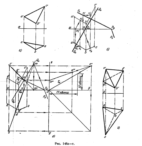
the y-axis is 10 units, and up to the z-axis is 17 units. The point S belongs to this plane. The profile projection s "of the top of the pyramid is located at the intersection m" n "with the trace T ω (in the figure, to simplify the drawing, the profile projection of the point D lying on the straight line MN is constructed). From s" we find s "and s. In Fig. 148, d projections of the desired pyramid are shown.
151. Triangle ABC is given (Fig. 149). Construct projections of the pyramid SABC, the vertex S of which is equidistant from the vertices of the base of ABC and lies in the square. v.

152*. Points A, L, M and N are given (Fig. 150, a). Construct a parallelogram ABCD whose vertex B lies on the square. H, side CD - on a straight line equidistant from points L, M and N, vertex D equidistant from planes V and H.
Solution. Since the side CD of the desired parallelogram must lie on a straight line equidistant from the three points, we start by constructing this straight line. A similar construction has already been encountered: the straight line EF is obtained as a line of intersection of two planes (Fig. 150, 6 and c) P and Q, drawn perpendicular to the segments LM and MN through their midpoints. Point D on this line is found from the condition that
it is equidistant from the square. V and pl. H (Fig. 150, d): we draw an auxiliary line f "5 through the point f at the same angle to the x-axis as the straight line f" e ", we get a point d on the projection ef, and along it d", moreover, d " 6 = d-6.
So, we got one of the vertices of the required parallelogram (point D) and the direction of the side passing through this point (straight line EF). Passing through the given

point A is a straight line parallel to EF, we get side AB, knowing that, by condition, point B must be in square. N.
It remains to complete the construction of the projections of the parallelogram by drawing a "b" and ab (Fig. 150.6), b "c" || a"d" and bc || ad. Points c" and c must be on the line of communication with" c, perpendicular to the x-axis.
153. Points A, L, M and N are given (Fig. 151). Construct a parallelogram ABCD whose vertex B lies on the square. H, side CD lies on a straight line equidistant from points L, M and N, vertex D is equidistant from pl. V and pl.H

154. Triangle ABC is given (Fig. 152). Construct projections of the pyramid SABC, the vertex S of which is equidistant from points A, B and C and is at equal distances from the square. V and pl. H.
INTERSECTION OF A LINE WITH A PLANE AND INTERCECTION OF TWO PLANES
Construction of the point of intersection of a straight line with a projecting plane reduces to constructing a second projection of a point on the diagram, since one projection of a point always lies on the trace of the projecting plane, because everything that is in the projecting plane is projected onto one of the traces of the plane. On fig. 224,a shows the construction of the point of intersection of the straight line EF with the front-projecting plane of the triangle ABC (perpendicular to the plane V) On the plane V, the triangle ABC is projected into the segment a "c" of the straight line, and the point k "will also lie on this line and be at the point the intersection of e "f" with a "c". A horizontal projection is built using a line of projection connection. The visibility of a straight line relative to the plane of the triangle ABC is determined by the relative position of the projections of the triangle ABC and the straight line EF on the plane V. The direction of view in Fig. 224, a is indicated by an arrow That section of the straight line, the frontal projection of which is above the projection of the triangle, will be visible. To the left of the point k "the projection of the straight line is above the projection of the triangle, therefore, this section is visible on the H plane.
On fig. 224, b, the straight line EF intersects the horizontal plane P. The frontal projection k "of the point K - the point of intersection of the straight line EF with the plane P - will be at the point of intersection of the projection e" f "with the trace of the plane Pv, since the horizontal plane is a front-projecting plane. The horizontal projection k of the point K is found using the projection connection line.
Construction of a line of intersection of two planes is reduced to finding two points common to these two planes. This is enough to construct an intersection line, since the intersection line is a straight line, and a straight line is defined by two points. When a projecting plane intersects with a plane in general position, one of the projections of the intersection line coincides with the trace of the plane located in the plane of projections to which the projecting plane is perpendicular. On fig. 225, and the frontal projection m "n" of the intersection line MN coincides with the trace Pv of the front-projecting plane P, and in fig. 225b, the horizontal projection kl coincides with the trace of the horizontally projecting plane R. Other projections of the intersection line are constructed using projection connection lines.

Construction of the point of intersection of a line with a plane general position (Fig. 226, a) is performed using an auxiliary projecting plane R, which is drawn through a given straight line EF. A line of intersection 12 of the auxiliary plane R with a given plane of the triangle ABC is built, two straight lines are obtained in the plane R: EF - a given line and 12 - a constructed line of intersection, which intersect at point K.

Finding the projections of the point K is shown in fig. 226b. Constructions are performed in the following sequence.
An auxiliary horizontal projection plane R is drawn through the straight line EF. Its trace R H coincides with the horizontal projection ef of the straight line EF.
A frontal projection 1"2" of the line of intersection 12 of the plane R with the given plane of the triangle ABC is built using projection lines, since the horizontal projection of the line of intersection is known. It coincides with the horizontal trace R H of the plane R.
The frontal projection k" of the desired point K is determined, which is located at the intersection of the frontal projection of this straight line with the projection 1"2" of the intersection line. The horizontal projection of the point is constructed using a projection connection line.
The visibility of a line with respect to the plane of triangle ABC is determined by the method of competing points. To determine the visibility of a straight line on the frontal plane of projections (Fig. 226, b), we compare the Y coordinates of points 3 and 4, the frontal projections of which coincide. The Y-coordinate of point 3, which lies on the line BC, is less than the Y-coordinate of point 4, which lies on the line EF. Consequently, point 4 is closer to the observer (the direction of view is indicated by an arrow) and the projection of the straight line is depicted on the visible plane V. The line passes in front of the triangle. To the left of the point K" the line is closed by the plane of the triangle ABC.
Visibility on the horizontal projection plane is shown by comparing the Z coordinates of points 1 and 5. Since Z 1 > Z 5 , point 1 is visible. Therefore, to the right of point 1 (up to point K), the line EF is invisible.

To construct a line of intersection of two planes in general position, auxiliary secant planes are used. This is shown in fig. 227 a. One plane is given by triangle ABC, the other is given by parallel lines EF and MN. The given planes (Fig. 227, a) are crossed by the third auxiliary plane. For ease of construction, horizontal or frontal planes are taken as auxiliary planes. AT this case the auxiliary plane R is the horizontal plane. It intersects the given planes along straight lines 12 and 34, which at the intersection give the point K, which belongs to all three planes, and, consequently, to two given ones, i.e., lying on the line of intersection of the given planes. The second point is found using the second auxiliary plane Q. The two points K and L found determine the line of intersection of the two planes.
On fig. 227b, the auxiliary plane R is given by the frontal wake. The frontal projections of the lines of intersection 1 "2" and 3"4 of the plane R with the given planes coincide with the frontal trace Rv of the plane R, since the plane R is perpendicular to the plane V, and everything that is in it (including the lines of intersection) is projected onto its frontal trace Rv. The horizontal projections of these lines are constructed using projection connection lines drawn from the frontal projections of points 1", 2", 3", 4" to the intersection with the horizontal projections of the corresponding lines at points 1, 2, 3, 4. Constructed the horizontal projections of the intersection lines are extended until they intersect with each other at point k, which is the horizontal projection of the point K belonging to the line of intersection of the two planes.The frontal projection of this point is on the trace Rv.
To construct the second point belonging to the line of intersection, a second auxiliary plane Q is drawn. For the convenience of construction, the plane Q is drawn through the point C parallel to the plane R. Then, to construct horizontal projections of the lines of intersection of the plane Q with the plane of the triangle ABC and with the plane given by parallel lines, it is sufficient find two points: c and 5 and draw straight lines through them parallel to the previously constructed projections of the intersection lines 12 and 34, since the plane Q ║ R. Continuing these lines until they intersect with each other, one obtains a horizontal projection l of the point L belonging to the line of intersection of the given planes. The frontal projection l" of the point L lies on the trace Q v and is constructed using the line of the projection connection. By connecting the projections of the same name of the points K and L, the projections of the desired intersection line are obtained.
If we take a line in one of the intersecting planes and construct a point of intersection of this line with another plane, then this point will belong to the line of intersection of these planes, since it belongs to both given planes. Let's build the second point in the same way, we can find the line of intersection of two planes, since two points are enough to build a straight line. On fig. 228 shows such a construction of the line of intersection of two planes given by triangles.

For this construction, one of the sides of the triangle is taken and the point of intersection of this side with the plane of the other triangle is built. If this fails, take the other side of the same triangle, then the third. If this did not lead to finding the desired point, the points of intersection of the sides of the second triangle with the first are built.
On fig. 228 the point of intersection of the line EF with the plane of the triangle ABC is constructed. To do this, an auxiliary horizontally projecting plane S is drawn through the straight line EF and a frontal projection 1 "2" of the line of intersection of this plane with the plane of the triangle ABC is built. The frontal projection 1 "2" of the intersection line, intersecting with the frontal projection e "f" of the straight line EF, gives the frontal projection m "of the intersection point M. The horizontal projection m of the point M is found using the projection connection line. The second point belonging to the line of intersection of the planes of the given triangles , - point N - the point of intersection of the line BC with the plane of the triangle DEF. Through the line BC, a front-projecting plane R is drawn, and on the plane H, the intersection of the horizontal projections of the line BC and the line of intersection 34 gives point n - the horizontal projection of the desired point. Visible sections of given triangles are determined using competing points for each projection plane separately.To do this, select a point on one of the projection planes, which is the projection of two competing points.Visibility is determined from the second projections of these points by comparing their coordinates.
For example, points 5 and 6 are the intersection points of the horizontal projections bc and de. On the frontal projection plane, the projections of these points do not coincide. Comparing their Z coordinates, they find out that point 5 closes point 6, since the Z 5 coordinate is greater than the Z 6 coordinate. Therefore, to the left of point 5, the side DE is invisible.
Visibility on the frontal plane of projections is determined using competing points 4 and 7 belonging to the segments DE and BC, comparing their coordinates Y 4 and Y 7 Since Y 4 > Y 7, the side DE on the plane V is visible.
It should be noted that when constructing the point of intersection of a straight line with the plane of a triangle, the point of intersection may be outside the plane of the triangle. In this case, by connecting the obtained points belonging to the intersection line, only that part of it that belongs to both triangles is outlined.
REVIEW QUESTIONS
1. What coordinates of a point determine its position in the V plane?
2. What is the Y coordinate and Z coordinate of a point?
3. How are the projections of the segment perpendicular to the plane of projections H located on the diagram? Perpendicular to the projection plane V?
4. How are the horizontal and frontal projections located on the diagram?
5. Formulate the main position about the belonging of a point to a straight line.
6. How to distinguish intersecting lines from intersecting ones in a diagram?
7. What points are called competing?
8. How to determine which of the two points is visible if their projections on the frontal projection plane coincide?
9. Formulate the main position about the parallelism of a straight line and a plane.
10. What is the procedure for constructing the point of intersection of a line with a plane in general position?
11. What is the procedure for constructing a line of intersection of two planes in general position?
