Construction of the third type on two known types.
Let the main view and the top view be known. It is necessary to build a view on the left.
Two main methods are used to build a third type according to two known ones.
Building a third view using an auxiliary line.
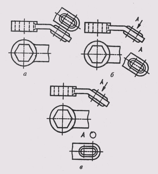
In order to transfer the size of the width of the part from the top view to the left view, it is convenient to use the auxiliary straight line (Fig. 27a, b). It is more convenient to draw this straight line to the right of the top view at an angle of 45° to the horizontal direction.
To build a third projection A 3 peaks BUT, draw through its frontal projection A 2 horizontal line 1 . It will contain the desired projection A 3. After that, through a horizontal projection A 1 draw a horizontal line 2 until it intersects with the auxiliary line at the point A 0. Through the dot A 0 draw a vertical line 3 to the intersection with the line 1 at the desired point A 3.
The profile projections of the other vertices of the object are constructed similarly.
After an auxiliary straight line is drawn at an angle of 45 °, it is also convenient to construct a third projection using a T-square and a triangle (Fig. 27b). First through frontal projection A 2 draw a horizontal line. Draw a horizontal line through the projection A 1 there is no need, it is enough, by applying a T-square, to make a horizontal notch at the point A 0 on the auxiliary line. After that, having slightly moved the T-square down, we apply the square with one leg to the T-square so that the second leg passes through the point A 0, and mark the position of the profile projection A 3.
Building a third view using baselines.
To construct the third view, it is necessary to determine which lines of the drawing should be taken as the base lines for measuring the dimensions of the object images. As such lines, they usually take axial lines (projections of the planes of symmetry of the object) and projections of the planes of the bases of the object. Let's take an example (Fig. 28) of building a view on the left according to two given projections of an object.
Rice. 27 Building a third projection from two data

Rice. 28. The second way to build a third projection from two data
Comparing both images, we establish that the surface of the object includes surfaces: regular hexagonal 1 and quadrangular 2 prisms, two cylinders 3 and 4 and truncated cone 5 . The object has a frontal plane of symmetry F, which is convenient to take as a base for measuring the width of individual parts of an object when constructing its view on the left. The heights of individual sections of the object are measured from the lower base of the object and are controlled by horizontal communication lines.
The shape of many objects is complicated by various cuts, cutouts, and intersections of the constituent surfaces. Then you first need to determine the shape of the intersection lines, build them on individual points, introducing the designations of the projections of the points, which, after completing the constructions, can be removed from the drawing.
On fig. 29, a left view of an object is constructed, the surface of which is formed by the surface of a vertical cylinder of rotation with T-shaped notch in its upper part and a cylindrical hole occupying a front-projecting position. The plane of the lower base and the frontal plane of symmetry were taken as base planes F. Image T-shaped notch in the left view built using points A, B, C, D and E the contour of the cut, and the line of intersection of cylindrical surfaces - using points K, L, M and they are symmetrical. When constructing the third type, the symmetry of the object relative to the plane is taken into account F.

Rice. 29. Building a view on the left
5.2.3. Construction of transition lines. Many details contain lines of intersection of various geometric surfaces. These lines are called transition lines. On fig. 30 shows a bearing cover, the surface of which is limited by surfaces of rotation: conical and cylindrical.
The intersection line is built using auxiliary cutting planes (see Section 4).
The characteristic points of the intersection line are determined.
The presentation shows algorithms for constructing the missing view according to two given ones. Three cases are considered: when either the front view, or the top view, or the left view is missing. The missing view is built on the drawing using external or internal coordination.
Download:
Preview:
To use the preview of presentations, create a Google account (account) and sign in: https://accounts.google.com
Slides captions:
Construction on the drawing of the missing view according to two given
Drawings of geometric bodies are referred to as projection drawing, and drawings of parts are referred to as technical. Therefore, images in projection drawings are called projections, and in technical drawings they are called views. In drawing, quite often there are tasks related to the construction of a third one according to two given types. The drawing may not have a left, top or front view - the main view. In all 3 cases, work on constructing the missing view is carried out according to a single algorithm.
Algorithm for constructing the missing view of the part according to two given ones According to the drawing, the geometric shape and symmetry of the parts are analyzed, and the missing view is established. Mentally represent a visual image of the part. (It is better to draw it to facilitate further work).
Based on the created visual image, the outline of the missing view is determined, its graphic composition is analyzed. Perform the construction of the missing view on the drawing, using external or internal coordination. Build: Dimensional rectangle and draw an axis of symmetry (if the image is symmetrical); Visible outlines of the part (either from reference points or via connection lines); invisible outlines. Apply dimensions. Circle the drawing.
Algorithm for constructing the missing part view using external coordination Left view Top view Front view Return to the algorithm
1. Build a dimensional rectangle of the missing view, using a constant straight line, and draw axes of symmetry 2 action Select view
2. Build the visible outlines of the image of the part on the missing view using connection lines 3 action Select the view 1 action
3. Invisible outlines of the image of the part are built using the lines of the projection connection View selection 2 action
Algorithm for constructing the missing part view using internal coordination Left view Top view Front view Return to the algorithm
2. Build the visible outlines of the image of the missing view from the reference point: Lower geometric body; Upper geometric body. 3 action View selection 1 action
3. Invisible outlines of the image of the missing part view are built by means of projection connection lines from reference points. View selection 2 action
1. A dimensional rectangle is built and axes of symmetry are drawn in it: projection lines are drawn from one of the given views that determine one of the dimensions of the dimensional rectangle; choose a reference point; measure on the second given form the second size of the dimensional rectangle; building a dimensional rectangle of the missing view from the reference point; draw an axis of symmetry 2 action View selection
1. A dimensional rectangle is built and axes of symmetry are drawn in it: projection lines are drawn from one of the given views that determine one of the dimensions of the dimensional rectangle; choose a reference point; measure on the second given form the second size of the dimensional rectangle; building a dimensional rectangle of the missing view from the reference point; draw an axis of symmetry 2 action View selection
2. Build the visible outlines of the image of the missing view from the reference point: Lower geometric body; Upper geometric body 3 action View selection 1 action
3. Invisible outlines of the image of the missing part view are built by means of projection connection lines from reference points View selection 2 action
You will need
- - a set of pencils for drawing of different hardness;
- - ruler;
- - square;
- - compass;
- - eraser.
Instruction
Sources:
- projection construction
The projection is strongly associated with the exact sciences - geometry and drawing. However, this does not prevent her from meeting all the time in distant, seemingly non-scientific and ordinary things: the shadow of an object that falls on a flat surface in sunlight, railway sleepers, any map and any drawing is already nothing else? like a projection. Of course, the creation of maps and drawings requires a deep study of the subject, but the simplest projections can be built independently, armed only with a ruler and a pencil.

You will need
- * pencil;
- * ruler;
- * paper.
Instruction
The first method of constructing a projection is central projection and is especially suitable for depicting objects on a plane when it is necessary to reduce or increase their actual size (Fig. a). The central design algorithm is as follows: we denote the design plane (P ") and the design center (S). To project ABC into the P plane, we draw through the center point S and points A, B and C AS, SB and SC. Their intersection with the plane P "forms points A", B "and C", when connected by straight lines, we get the central projection ABC.

The second method differs from the one described above only in that the straight lines, with the help of which the vertices of the triangle ABC are projected into the plane P ", are not, but parallel to the designated projection direction (S). Nuance: the projection direction cannot be parallel to the plane P". When connecting design points A"B"C" we get a parallel projection.
Despite the simplicity, the skill of constructing such simple projections helps to develop spatial thinking and can boldly step into descriptive.

Related videos
One of the most fascinating tasks of descriptive geometry is the construction of a third kind given two. It requires a thoughtful approach and pedantic measurement of distances, so it is not always given the first time. However, if you carefully follow the recommended sequence of actions, it is quite possible to build a third view, even without spatial imagination.

You will need
- - paper;
- - pencil;
- - ruler or compasses.
Instruction
First of all, try on the two available kind m to determine the shape of the individual parts of the depicted object. If the top view shows a triangle, then it can be a prism, cone of revolution, triangular or. The shape of a quadrangle can be taken by a cylinder, or a triangular prism, or other objects. The image in the form of a circle can mean a sphere, a cone, a cylinder, or other surfaces of revolution. Either way, try to imagine the overall shape of the object as a whole.
Draw the boundaries of the planes, for the convenience of transferring lines. Start with the most convenient and understandable element. Take any point that you exactly "see" on both kind x and move it to the third view. To do this, lower the perpendicular to the boundaries of the planes and continue it on the next plane. Please note that when switching from kind from the left to the top view (or vice versa), you must use a compass or measure the distance with a ruler. So in place of your third kind two lines intersect. This will be the projection of the selected point on the third view. In the same way, as many points as you like are possible until you understand the general appearance of the part.
Check if the build is correct. To do this, measure the dimensions of those parts of the part that are completely (for example, a standing cylinder will be the same "height" in the left and front views). In order to, if you don’t do anything, try from the position of the observer from above and count (at least approximately) how much the boundaries of holes and surfaces should be visible. Every straight line, every point must be reflected in all kind X. If the part is symmetrical, do not forget to mark the axis of symmetry and check the equality of both parts.
Delete all auxiliary lines, check that all invisible lines are marked with a dotted line.
To depict this or that object, first its individual elements are depicted in the form of the simplest figures, and then their projection is performed. Projection construction is quite often used in descriptive geometry.

You will need
- - pencil;
- - compass;
- - ruler;
- - reference book "Descriptive geometry";
- - elastic.
Instruction
Carefully read the conditions of the task: for example, given the frontal projection F2. The point F belonging to it is located on the side of the cylinder. It is required to build three projections F. Mentally imagine how it all should look, then proceed to building an image.

A cylinder of rotation can be represented as a rotating rectangle, one of the sides of which is taken as the axis of rotation. The second rectangle - opposite to the axis of rotation - is the lateral surface of the cylinder. The rest represent the lower and upper cylinders.
Due to the fact that the surface of the cylinder of revolution when constructing the given projections is made in the form of a horizontally projecting surface, the projection of the point F1 must necessarily coincide with the point P.
Draw the projection of the point F2: since F is on the front surface of the cylinder of revolution, the point F2 will be the point F1 projected onto the lower base.
Build the third projection of the point F using the y-axis: put F3 on it (this projection point will be located to the right of the z3 axis).
Related videos
note
When constructing image projections, follow the basic rules used in descriptive geometry. Otherwise, the projection will fail.
Helpful advice
To build an isometric image, use the top base of the rotation cylinder. To do this, first build an ellipse (it will be located in the x"O"y" plane). After that, draw the tangent lines and the lower half-ellipse. Then draw a coordinate polyline and use it to construct the projection of the point F, that is, the point F".
Sources:
- Construction of projections of points belonging to a cylinder and a cone
- how to plot a cylinder projection
Horizontals - isohypses (lines of equal heights) - lines that connect points on the earth's surface that have the same height marks. The construction of contour lines is used to compile topographic and geographical maps. Contours are built on the basis of measurements by theodolites. The exit points of the cutting planes are projected outward onto horizontal plane.

Instruction
The level surface for counting horizontals in Russia is considered to be the zero of the Kronstadt footstock. It is from her that the contour lines are counted, which makes it possible to interconnect individual plans and maps compiled by various organizations. Horizontal lines determine not only the earth's relief, but also the relief of water basins. Isobaths (water contour lines) connect points of equal depth.
To designate the relief, universal conventional signs are used, which are contour (scale), off-scale and explanatory. In addition, there are additional elements that accompany conventional signs. To them are all kinds of inscriptions, rivers, color schemes of cards.
There are two ways to build a horizontal line on a plan between two points: graphical and analytical. For a graphical construction of a horizontal line on a plan, take graph paper.
Draw several horizontal parallel lines on paper at equal distances. The number of lines is determined by the number of required sections between two points. The distance between lines is assumed to be equal to the given distance between contour lines.
Draw two vertical parallel lines at a distance equal to the distance between the given points. Mark these points on them, taking into account their height (altitude). Connect the dots with a slanted line. The points of intersection of the line of horizontal lines are the exit points of the secant planes to the outside.
Transfer the segments obtained as a result of the intersection to horizontal a straight line connecting two given points using the orthogonal projection method. Connect the obtained points with a smooth line.
To construct contour lines using the analytical method, formulas derived from features are used. In addition to these methods, computer programs such as Archikad and Architerra are also used today to build horizontal lines.
Related videos
Sources:
- horizontal is like in 2019
When creating an architectural project or developing an interior design, it is very important to imagine how the object will look in space. Axonometric projection can be used, but is good for small items or details. The advantage of frontal perspective is that it gives an idea not only of the appearance of the object, but allows you to visually represent the ratio of sizes depending on the distance.

You will need
- - paper;
- - pencil;
- - ruler.
Instruction
The principles of building a frontal perspective are the same for a Whatman sheet and a graphic editor. So do it on a sheet. If the item is small, A4 size will suffice. For a frontal perspective or interior, take a leaf. Lay it horizontally.
For a technical drawing or drawing, select the scale. For the standard, take some clearly distinguishable parameter - for example, buildings or the width of a room. Draw an arbitrary segment on the sheet corresponding to this line, and calculate the ratio.
This one will become the base of the picture plane, so place it at the bottom of the sheet. Designate the end points, for example, as A and B. For a picture with a ruler, you do not need to measure anything, but determine the ratio of the parts of the object. The sheet must be larger than the picture plane in order to
The image of the visible part of the surface of the object facing the observer is called the view.
GOST 2.305-68 establishes the following name for the main views obtained on the main projection planes (see Fig. 1.1.1): 7 - front view (main view); 2 - top view; 3 - left side view; 4 - right side view; 5 - bottom view; b - rear view. In practice, three views are more widely used: front view, top view and left view.
The main views are usually located in a projection relationship with each other. In this case, the name of the views on the drawing does not need to be inscribed.
If any view is displaced relative to the main image, its projection connection with the main view is broken, then an “A” type inscription is made above this view (Fig. 1.2.1).

The direction of view should be indicated by an arrow marked with the same capital letter of the Russian alphabet as in the inscription above the view. The ratio of the sizes of the arrows indicating the direction of view should correspond to those shown in fig. 1.2.2.
If the views are in a projection relationship with each other, but are separated by any images or are located on more than one sheet, then an inscription of the “A” type is also made above them. An additional view is obtained by projecting an object or part of it onto an additional projection plane that is not parallel to the main planes (Fig. 1.2.3). Such an image must be performed in the case when any part of the object is not depicted without distorting the shape or size on the main projection planes.
An additional projection plane in this case can be located perpendicular to one of the main projection planes.
When an additional view is located in direct projection connection with the corresponding main view, it is not necessary to designate it (Fig. 1.2.3, a). In other cases, an additional view should be marked on the drawing with an inscription of type "A" (Fig. 1.2.3, b),

and for the image associated with the additional view, you need to put an arrow indicating the direction of the view, with the corresponding letter designation.
The secondary view can be rotated while maintaining the position adopted for this item in the main image. In this case, a sign must be added to the inscription (Fig. 1.2.3, c).
A local view is an image of a separate, limited place on the surface of an object (Fig. 1.2.4).
If the local view is located in direct projection connection with the corresponding images, then it is not indicated. In other cases, local views are designated similarly to additional types; a local view can be limited by a cliff line (“B” in Fig. 1.2.4).
Top of page
Topic 3. Construction of the third type of object according to two data
First of all, you need to find out the shape of the individual parts of the surface of the depicted object. To do this, both given images must be viewed simultaneously. It is useful to keep in mind which surfaces correspond to the most common images: triangle, quadrilateral, circle, hexagon, etc.
On the top view in the form of a triangle, they can be depicted (Fig. 1.3.1, a): triangular prism 1, triangular 2 and quadrangular 3 pyramids, cone of revolution 4.

An image in the form of a quadrangle (square) can be seen from above (Fig. 1.3.1, b): a cylinder of rotation 6, a triangular prism 8, quadrangular prisms 7 and 10, as well as other objects limited by planes or cylindrical surfaces 9.
The shape of a circle can be seen from above (Fig. 1.3.1, c): ball 11, cone 12 and cylinder 13 of rotation, other surfaces of rotation 14.
The top view in the form of a regular hexagon has a regular hexagonal prism (Fig. 1.3.1, d), which limits the surfaces of nuts, bolts and other parts.
Having determined the shape of individual parts of the surface of an object, one must mentally imagine their image in the left view and the entire object as a whole.
To construct the third view, it is necessary to determine which lines of the drawing should be taken as the base for reporting the dimensions of the object image. As such lines, axial lines are usually used (projections of the planes of symmetry of the object and projections of the planes of the bases of the object). Let's analyze the construction of the view on the left using an example (Fig. 1.3.2): according to the main view and the top view, construct a left view of the depicted object.
Comparing both images, we establish that the surface of the object includes surfaces: regular hexagonal 1 and quadrangular 2 prisms, two cylinders 3 and 4 of rotation and a truncated cone 5 of rotation. The object has a frontal plane of symmetry Ф, which is convenient to take as the basis for reporting the dimensions of the width of individual parts of the object when constructing its view on the left. The heights of individual sections of the object are measured from the lower base of the object and are controlled by horizontal communication lines.


The shape of many objects is complicated by various cuts, cuts, and intersections of the surface components. Then you first need to determine the shape of the intersection lines, and you need to build them by individual points, introducing the designations of the projections of the points, which, after completing the constructions, can be removed from the drawing.
On fig. 1.3.3, a left-hand view of an object is constructed, the surface of which is formed by the surface of a vertical cylinder of revolution, with a T-shaped notch in its upper part and a cylindrical hole with a frontally projecting surface. The plane of the lower base and the frontal plane of symmetry F were taken as base planes. M and im symmetrical. When constructing the third type, the symmetry of the object with respect to the F plane was taken into account.
Top of page
A complete technical drawing contains at least three projections. However, the knowledge to imagine an object in two projections is required from both the technologist and the skilled worker. It is consequently that in the examination papers in technical universities and colleges there are continuously problems for the construction of the third type according to two given ones. In order to successfully complete a similar task, you need to know the conventions adopted in technical drawing.
You will need
- - paper;
- - 2 projections of the part;
- - drawing tools.
Instruction
1. The theses for constructing the third type are identical for classical drawing, sketching and drawing in one of the computer programs prepared for this. Before each, analyze the given projections. See what kind you are given. When it comes to 3 views, it is the general projection, the top view and the left view. Determine what is given to you. This can be done according to the location of the drawings. The left view is located on the right side of the general, and the top view is below it.
2. Establish a projection link to one of the given views. This can be done by extending the horizontal lines that limit the silhouette of the object to the right, when you want to build a view from the left. If we are talking about a top view, continue down the vertical lines. In any case, one of the part parameters in your drawing will appear mechanically.

3. Find the 2nd parameter on the existing projections, which limits the silhouettes of the part. When constructing a view on the left, you will find this size in the top view. When establishing a projection relationship with the main view, the height of the part appeared in your drawing. So, from the top view, you need to take the width. When constructing a top view, the 2nd dimension is taken from the side projection. Mark the silhouettes of your object in the third projection.

4. See if the part has protrusions, voids, holes. This is all noticed on the general projection, which, by definition, should give the most accurate idea of the subject. True, just as when determining the general silhouette of a part in the third projection, establish a projection connection between different elements. The remaining parameters (say, the distance from the center of the hole to the edge of the part, the depth of the protrusion, etc.) are found in the side or top view. Build the necessary elements, considering the measurements you have found.

5. In order to check how well you coped with the task, try to draw a detail in one of the axonometric projections. See how reasonably the elements of the third type you have drawn are located on the volumetric projection. It may well be that you will have to make some adjustments to the drawing. A drawing with perspective can also help to check your construction.
One of the most interesting problems in descriptive geometry is the construction of a third kind for given 2. It requires a thoughtful approach and a meticulous measurement of distances, therefore it is not invariably given the first time. However, if you carefully follow the recommended sequence of actions, erecting the 3rd type is absolutely acceptable, even without spatial imagination.
You will need
- - paper;
- - pencil;
- - ruler or compasses.
Instruction
1. First of all, try on the two available kind m to determine the shape of the individual parts of the depicted object. If a triangle is shown in the top view, then it can be a triangular prism, a cone of revolution, a triangular or quadrangular pyramid. The shape of a quadrangle can be taken by a cylinder, a quadrangular or triangular prism, or other objects. An image in the form of a circle can represent a sphere, a cone, a cylinder, or other surfaces of revolution. One way or the other, try to imagine the general form of the object in the aggregate.
2. Draw the boundaries of the planes, for the comfort of transferring lines. Start the transfer with the most comfortable and intelligible element. Take any dot that you correctly "see" on both kind x and move it to the 3rd view. To do this, lower the perpendicular to the boundaries of the planes and continue it on a further plane. Please note that when switching from kind on the left in the top view (or opposite), you need to use a compass or measure the distance with a ruler. So in place of your third kind two lines intersect. This will be the projection of the selected point on the 3rd view. In the same way, it is allowed to transfer as many points as desired, until the general view of the part becomes clear to you.
3. Check if the build is correct. To do this, measure the dimensions of those parts of the part that are reflected entirely (say, a standing cylinder will be the same "height" in the left and front views). In order to realize that you have not forgotten anything, try to look at the front view from the position of the observer from above and count (though approximately) how much the boundaries of holes and surfaces should be visible. The whole line, every point must be reflected on all kind X. If the part is symmetrical, do not forget to mark the axis of symmetry and check the equality of both parts.
4. Delete all auxiliary lines, check that all noticeable lines are marked with a dotted line.
In order to depict this or that object, its individual elements are first depicted in the form of simple figures, and then their projection is performed. Projection construction is often used in descriptive geometry.
You will need
- - pencil;
- - compass;
- - ruler;
- - reference book "Descriptive Geometry";
- - elastic.
Instruction
1. Carefully read the data of the task: for example, the general projection F2 is given. The point F belonging to it is located on the lateral surface of the cylinder of revolution. It is required to build 3 projections of point F. Mentally imagine how it all should look, then proceed to build an image on paper.
2. A cylinder of rotation can be represented as a rotating rectangle, one of the sides of which is taken as the axis of rotation. The second side of the rectangle - opposite to the axis of rotation - forms the side surface of the cylinder. The remaining two sides represent the bottom and top base of the cylinder.
3. Due to the fact that the surface of the cylinder of revolution when constructing the given projections is made in the form of a horizontally projecting surface, the projection of the point F1 must certainly coincide with the point P.
4. Draw the projection of the point F2: since F is on the common surface of the cylinder of revolution, the point F2 will be the point F1 projected onto the lower base.
5. Build the third projection of the point F using the y-axis: put F3 on it (this projection point will be located to the right of the z3 axis).
Related videos
Note!
When constructing image projections, follow the basic rules used in descriptive geometry. Otherwise, the projection will fail.
Helpful advice
To build an isometric image, use the top base of the rotation cylinder. To do this, first build an ellipse (it will be placed in the x'O'y' plane). After that, draw tangent lines and the lower half-ellipse. After that, draw a coordinate polyline and, with its support, construct the projection of the point F, that is, the point F’.
There are not so many people in our time who have never in their lives been able to draw or draw something on paper. Knowing how to execute a primitive drawing of some kind of construction is occasionally quite useful. It is allowed to spend a lot of time explaining “on the fingers” how this or that thing is made, while one glance at its drawing is enough to realize it without every word.

You will need
- - sheet of drawing paper;
- – drawing accessories;
- - drawing board.
Instruction
1. Select the sheet format on which the drawing will be made - in accordance with GOST 9327-60. The format should be such that it is allowed to place the main kinds details in the appropriate scale, as well as all the necessary cuts and sections. For simple parts, choose A4 (210x297 mm) or A3 (297x420 mm) format. The 1st can be located with its long side only vertically, the 2nd - vertically and horizontally.
2. Draw a drawing frame, stepping back from the left edge of the sheet 20 mm, from the rest 3 - 5 mm. Draw the main inscription - a table in which all data about details and drawing. Its dimensions are determined by GOST 2.108-68. The width of the core inscription is constant - 185 mm, the height varies from 15 to 55 mm, depending on the purpose of the drawing and the type of institution for which it is performed.
3. Select the main image scale. Permissible scales are determined by GOST 2.302-68. They should be preferred such that all the main elements are perfectly visible on the drawing. details. If at the same time some places are not clearly visible, they can be transferred in a separate view, showing with the necessary magnification.
4. Select main image details. It should be such a direction of looking at the part (projection direction), from which its design is revealed most fully. In most cases, the main image is the location in which the part is on the machine during the core operation. Parts that have an axis of rotation are located on the main image, as usual, so that the axis has a horizontal arrangement. The main image is located in the upper part of the drawing on the left (if there are three projections) or close to the center (if there is no side projection).
5. Determine the location of the remaining images (side view, top view, sections, cuts). Kinds details are formed by its projection onto three or two mutually perpendicular planes (Monge's method). In this case, the part must be located in such a way that the set or all of its elements are projected without distortion. If any of these views is informational redundant, don't do it. The drawing should have only those images that are needed.
6. Select cuts and sections to be executed. Their difference from each other lies in the fact that the section shows what is behind the cutting plane, while the section displays only what is located in the plane itself. The cutting plane can be stepped or broken.
7. Proceed at ease to drawing. When drawing lines, follow GOST 2.303-68, which defines kinds lines and their parameters. Place the images at such a distance from each other that there is enough space for sizing. If the cut planes pass through the monolith details, hatch the sections with lines going at an angle of 45°. If at the same time the hatching lines coincide with the main lines of the image, it is allowed to draw them at an angle of 30 ° or 60 °.
8. Draw dimension lines and mark dimensions. In doing so, follow the following rules. The distance from the first dimension line to the silhouette of the image must be at least 10 mm, the distance between adjacent dimension lines must be at least 7 mm. Arrows are required to have a length of about 5 mm. Write numbers in accordance with GOST 2.304-68, take their height equal to 3.5-5 mm. Place the numbers closer to the middle of the dimension line (but not on the image axis) with some offset relative to the numbers on adjacent dimension lines.
Related videos
Performing an accurate drawing repeatedly requires large expenditures of time. Consequently, in case of an urgent need to make some part, it is often not a drawing that is made, but a sketch. It is performed quite quickly and without the use of drawing tools. At the same time, there are a number of requirements that the sketch must meet.

You will need
- - detail;
- - paper;
- - pencil;
- - measuring instruments.
Instruction
1. The sketch must be accurate. According to him, the person who will make a copy of the part should get an idea of both the appearance of the product and its design features. Therefore, before each observantly inspect the object. Determine the relationship between the various parameters. See if there are holes, where they are, their size and the ratio of diameter to the overall size of the product.
2. Decide which view will be the main view and how accurate it represents the part. The number of projections depends on this. There may be 2, 3 or more. How many projections you need depends on their location on the sheet. You need to proceed from how difficult the product will be.
3. Choose a scale. It should be such that the master can easily make out even the smallest details.
4. Start sketching with center and center lines. In the drawings, they are usually indicated by a dotted line with dots between the strokes. These lines indicate the middle of the part, the center of the hole, etc. They remain on the working drawings.
5. Draw the outer silhouettes of the part. They are indicated by a thick permanent line. Take care to correctly convey the ratio of sizes. Draw inner (noticeable) outlines.
6. Complete the cuts. This is done exactly the same as in any other drawing. The solid surface is shaded with oblique lines, the voids remain unfilled.
7. Draw dimension lines. From the points, the distance between which you want to designate, parallel vertical or horizontal strokes depart. Between them, draw a straight line with arrows at the ends.
8. Measure detail. Specify the length, width, hole diameters and other dimensions needed for precise work. Write the dimensions on the sketch. If necessary, apply signs indicating the methods and qualities of processing different surfaces of the product.
9. The final stage of work is filling the stamp. Enter your product information into it. In technical universities and design organizations, there are standards for filling stamps. If you are making a sketch for yourself, then it is allowed to indicate primitively what kind of part it is, the material from which it is made. The one who will make the part should see all other data in your sketch.
Related videos
The drawing serves to ensure that the one who will grind a part or build a house can get the most accurate idea of the appearance of the object, its structure, the ratio of parts, surface treatment methods. One projection for this, as usual, is unsatisfactory. In training drawings, three types are usually performed - the main one, on the left and on top. For objects of difficult shape, right and rear views are also used.

You will need
- - detail;
- — measuring instruments;
- - drawing tools;
- - computer with AutoCAD.
Instruction
1. The sequence of drawing on a sheet of Whatman paper and in AutoCAD is approximately identical. Look at the details first. Determine which angle will give the most accurate idea of the form and functional features. This projection will become its main view.
2. See if your part looks identical when viewed from the right and left. Not only the number of projections depends on this, but also their location on the sheet. The left view is located to the right of the main one, and the right view is, respectively, to the left. At the same time, in a flat projection, they will look as if they are at ease in front of the observer's eyes, that is, without perspective control.
3. Drawing construction methods are identical for all projections. Mentally position the object in the system of planes on which you will project it. Analyze the shape of the object. See if it is permissible to divide it into more primitive parts. Answer the question, in the form of which body it is allowed to completely inscribe your object in its entirety or any of its fragments. Imagine how the individual parts look in orthogonal projection. The plane on which the object is projected when constructing the view on the left is located on the right side of the object itself.
4. Measure the item. Remove the main parameters, set the ratio between the whole object and its individual parts. Select the scale and draw the main view.
5. Select a build method. There are two of them. To complete the drawing using the removal technique, first apply the general silhouettes of the object, on the one that you are looking to the left or right. After that, gradually begin to remove volumes, drawing recesses, silhouettes of holes, etc. When receiving an increment, one element is first drawn, and then the rest are slowly added to it. The choice of method depends primarily on the difficulty of the projection. If the detail, when viewed from the left or right, is a clearly defined geometric figure with a small number of deviations from the severe form, it is more comfortable to use the removal technique. If there are a lot of fragments, and the part itself cannot be entered into any figure, it is better to stepwise attach the elements to each other. The difficulty of the projections of the same part can be different, and therefore the methods can be changed.
6. In any case, start building the side view with the bottom and top lines. They must be on the same tier as the corresponding lines of the main view. This will provide a projection connection. Later, apply the general silhouettes of the part or its first fragment. Observe the ratio of sizes.
7. After drawing the overall silhouettes of the side view, apply centerlines, hatches, etc. Dimension it. It is not always necessary to sign a projection. If all views of the part are located on one sheet, then only the rear view is signed. The location of the remaining projections is determined by the standards. If the drawing is made on several sheets and one or both side views are not on the sheet on which the main one is, they need to be signed.
Related videos
Helpful advice
When constructing a side view in AutoCAD or another drawing program, it is not strictly necessary to combine the top and bottom lines of the main and side views at the first stage. It is allowed to execute the drawing in fragments, and combine the tiers when you start preparing it for printing.
