In cases where it is required to indicate the size of the diameter, use a sign in the form of a circle with a line "Ø". This symbol is applied before the dimension number.
Examples of using the diameter sign:
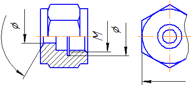
Diameter signs on cylindrical and conical revolving parts

Dimensions applied when there is not enough space
on the dimension line

Designation of dimensions in case of lack of space
for shooters
Diameter is the length of the line segment connecting the circle surfaces. The diameter segment, in any case, passes only through the center of the circle. It is usually denoted by the Latin letter "D" or the sign "Ø". If the radius of a circle is multiplied by two, the sum is the diameter. All volumetric bodies having a spherical shape, as well as those, at least one of the possible sections of which is a circle, are indicated by the symbols of diameter. Word " diameter"comes from the Greek word" diametros"- cross section.

Example of marking four holes
with diameter
On technical drawings, diameters are indicated by the crossed-out circle symbol “Ø”. This sign is placed in front of the dimensional numbers of parts, which can be both cylindrical and conical.
In section, the cone is a right triangle, one of the legs of which is parallel or parallel to the body of revolution. Its parameters have the following designations: "D" - a larger diameter, "d" - a smaller diameter, "L" - length. In the drawing, the diameters of the cone are indicated by numbers, preceded by the signs "Ø" and the numerical value of the length without letters.
The most common parts with cylindrical surfaces include shafts for various purposes. Cylindrical bodies formed by the rotation of a rectangle about one of its sides are denoted by the diameter. Smooth shafts have some design features, and are divided into varieties: straight, stepped one-sided, stepped double-sided and heavy. For example, the shafts of asynchronous motors, in which the rotor mates with the shaft by pressing it to its largest diameter, and on both sides there are steps for bearings, fans, and pulleys. Double-sided stepped shafts can also be found in various mechanisms where any other design features are required. Cylindrical parts, as a rule, have an overall maximum length and outer diameter. Depending on the specific configuration of a particular product, it may include such elements as internal and external grooves, steps, grooves, etc. with different diameters, the values of which are preceded by the signs "Ø".

Diameter sign example
on a spherical surface
Parts with conical surfaces include tool adapter sleeves, which have a conical outer and inner surface. Such bushings provide high centering accuracy and fast tool change with sufficient rigidity when used on machine tools. Adapter sleeves are short and long.
Conical tool parts of this type are called " morse taper and are divided into numbers. Angles, lengths and diameters of adapter sleeves can be taken from special tables. The tabular data uses letter designations such as - “d” is the smaller diameter, “D” is the large diameter, “L” is the length of the part. In the drawings, diameters and lengths are indicated by numerical values, and the “Ø” sign is placed in front of the diameter numbers.
« Morse taper» - in addition to adapter sleeves, it is used in the manufacture of twist drill shanks, end mills, fixtures and mandrels. Tool cones are fixed due to elastic and plastic deformation. To implement such connections in the spindles of milling and turning machines, conical holes are provided for installing auxiliary tools. In addition, on a lathe, the tailstock quill has the same tapered hole.
In technology, a large number of parts and their elements are used to designate which the diameter sign is used. For standard diameter sizes, a parametric series is used, which includes standard sizes. When developing technical products, the calculated diameters are rounded up to their nearest values. When designating on technical drawings, the diameter sign must be accompanied by the designation of the axis with a dash-dotted line, which indicates a circular section of the part section.
The basis for determining the size of the product and its elements are the dimensional numbers printed on the drawing. Dimensions always indicate true, regardless of the scale and accuracy of the image. Dimensions must be assigned and plotted so that they can be used to manufacture a part without resorting to calculations.
There should be a minimum number of sizes, but sufficient for the manufacture and control of the product.. The absence of at least one of the dimensions makes the drawing practically unusable. Dimensions should be applied so that when reading them there are no ambiguities or questions. It should be remembered that the drawing is read in the absence of the author.
According to GOST 2.307-2011 - "Application of dimensions and maximum deviations" linear dimensions in the drawing they are given in millimeters, without designating the unit of measurement. Angle dimensions indicate in degrees, minutes, seconds with the designation of the unit of measurement. Each size is applied on the drawing, in the main inscription only once, it is unacceptable to repeat it.
When specifying the dimensions of straight segments, dimension lines are drawn parallel to these segments at a distance of at least 10 mm from the contour line and 7 mm from each other, and extension lines are drawn perpendicular to the dimension lines. The extension lines should extend beyond the ends of the arrows of the dimension line by 1 ... 5 mm. The arrow of the dimension line must have a length of at least 2.5 mm and an angle at the top of about 20 ° (Figure 3.1). The dimensions and shape of the arrows must be the same throughout the drawing.
3.2. Dimensioning
On the drawings of parts, dimensions are affixed based on the manufacturing technology of this part and on what surfaces this part comes into contact with other parts of the assembly unit.
This affects the choice of design base.
basing is called giving the workpiece the required position relative to the selected coordinate system.
base a surface or a combination of surfaces, an axis or a point belonging to a product or workpiece and used for basing is called.
Design base- the base used to determine the position of the part or assembly unit in the product.
Basic rule for sizing- grouping of dimensions related to one geometric element in one image, on the one in which this element is most clearly represented. It is not always possible to achieve this, but we always strive for this.
When specifying the size of the corner, the dimension line is drawn in the form of an arc with the center at its vertex, and the extension lines are drawn radially (Figure 3.2).
Figure 3.3
As you can see, smaller dimensions should be placed closer to the contour of the part, the number of intersections of dimension and extension lines will be reduced, which will make it easier to read the drawing.
The dimension line is drawn with a break if it is not possible to draw an extension line on one side of the image, for example, if the view and section are combined (Figure 3.4, a), as well as if the view or section of a symmetrical object is depicted only up to the axis or with a break (Figure 3.4, b). A break in the dimension line is made further than the axis or break line of the object.
 |
|
| a | b |
Figure 3.4
Dimension lines can be drawn with a break in the following cases:
- when specifying the size of the diameter of the circle; at the same time, a break in the dimension line is made further than the center of the circle (Figure 3.5);
- when applying dimensions from a base not shown in this drawing (Figure 3.6).
 |
|
| Figure 3.5 | Figure 3.6 |
The main line must be interrupted if it intersects with an arrow (Figure 3.5).
When depicting a product with a break, the dimension line is not interrupted (Figure 3.7). The dimension number, in this case, must correspond to the total length of the part.

Figure 3.7
If it is not possible to place dimensional numbers and arrows between closely spaced solid main or thin lines, they are applied outside (Figure 3.8). The same is done when applying the size of the radius, if the arrow does not fit between the curve and the center of the radius (Figure 3.9).
 |
|
| Figure 3.8 | Figure 3.9 |
It is allowed to replace the arrows with dots or serifs applied at an angle of 45 ° to the dimension lines, if it is impossible to place an arrow between the extension lines (Figure 3.10).

Figure 3.10
Dimensional numbers are not allowed to be divided or crossed by any lines of the drawing. In the place where the dimension number is applied, the axial, center lines or hatching lines are interrupted (Figure 3.11).

Figure 3.11
Dimensional numbers should be applied above the dimension line, as close as possible to its middle (Figure 3.12).

Figure 3.12
Dimensional numbers of linear dimensions with different slopes of dimension lines are arranged as shown in Figure 3.13.
If it is necessary to apply the dimensions of the shaded area, the corresponding dimension number is applied on the shelf of the line - callouts.

Figure 3.13
Angular dimensions are applied as shown in Figure 3.14.

Figure 3.14
In the area located above the horizontal center line, dimension numbers are placed above the dimension lines from the side of their convexity, in the area located below the horizontal center line - from the side of the concavity of the dimension line.
Dimension numbers above parallel dimension lines should be staggered (Figure 3.15).

Figure 3.15
When specifying the size of the diameter, in all cases, the sign Ø is applied before the size number. Before the dimension number of the diameter (radius) of the sphere, the sign “O” Ø (R) is also applied without the inscription “Sphere” (Figure 3.16).

Figure 3.16
If it is difficult to distinguish the sphere from other surfaces in the drawing, it is allowed to put the word "Sphere" or the sign "O", for example, "Sphere Ø 18, OR12". The diameter of the sign of the sphere is equal to the height of the dimensional numbers in the drawing.
The dimensions of the square are applied as shown in the drawing (Figure 3.17).

Figure 3.17
The height of the sign must be equal to the height of the dimensional numbers in the drawing.
When drawing a radius dimension, a capital letter is placed in front of the dimension number R. With a larger radius, it is allowed to bring the center closer to the arc, in this case, show the dimension line of the radius with a break at an angle of 90 ° (Figure 3.18). If it is not required to specify the dimensions that determine the position of the center of the circular arc, then the radius dimension line may not be brought to the center and shifted relative to the center (Figure 3.19).
 |
|
| Figure 3.18 | Figure 3.19 |
Rounding radii, the size of which is 1 mm or less on the scale of the drawing, are not shown in the drawing and their dimensions are applied, as shown in Figure 3.20.
When drawing the size of an arc of a circle, the dimension line is drawn concentric to the arc, and the extension lines are parallel to the bisector of the angle, and the sign “” is applied above the dimension number (Figure 3.21).
 |
|
| Figure 3.20 | Figure 3.21 |
The dimensions of the 45° chamfers are applied as shown in Figure 3.22, a. A chamfer at an angle of 45 ° is allowed, the size of which is 1 mm or less on the scale of the drawing, not to be depicted and its dimensions to be indicated on the shelf of the line - leader, as shown in Figure 3.22, b.
The dimensions of chamfers with other angles are applied according to the general rules - two linear dimensions or linear and angular dimensions (Figure 3.23).
The question of what dimensions should be applied to the drawing is decided taking into account the technology for manufacturing parts and manufacturing control.
As a rule, the dimensions of full circles are set by the diameter, incomplete circles - by the radius.
When it is required to set the distances between circles, for example, representing holes, the distances between the centers of the circles and the distance from the center of any circle to one of the surfaces of the part are specified.
 |
|
| a | b |
Figure 3.22

Figure 3.23
The surfaces from which the dimensions of other elements of the part are set are called base surfaces or bases.
There are several ways to apply dimensions:
- from the common base (Figure 3.24); the left surface of the plank is selected as the base surface, from which the dimensions of all holes are marked.
Such a system has the advantage, but the dimensions are independent of each other, the error of one of them is not reflected in the others.
- from several bases (Figure 3.25);
- chain (Figure 3.26).

Figure 3.24

Figure 3.25

Figure 3.26
When applying dimensions that determine the distance between evenly spaced identical elements of the product (for example, holes), it is recommended that instead of dimensional chains, apply the size between adjacent elements and the size between the extreme elements in the form of the product of the number of gaps between the elements and the size of the gap (Figure 3.27).
With a large number of dimensions drawn from a common base, it is allowed to apply linear and angular dimensions, as shown in Figure 3.28, while drawing a common dimension line from the “0” mark and dimension numbers are applied in the direction of extension lines at their ends.

Figure 3.27

Figure 3.28
It is allowed not to apply the dimensions of the radius of conjugation of parallel lines on the drawing (Figure 3.29).

Figure 3.29
The outer and inner contours of parts during manufacture and control are measured separately, therefore, their dimensions should be applied separately on the drawing (Figure 3.30).

Figure 3.30
Dimensions related to the same structural element (groove, protrusion, hole, etc.) are recommended to be grouped in one place, placing them on the image in which the geometric shape of this element is shown most fully (Figure 3.31).

Figure 3.31
If the part has roundings, the dimensions of the parts of the part are applied without taking into account the roundings, indicating the radii of the roundings (Figure 3.32).

Figure 3.32
The dimensions of symmetrically located elements of the product (except for holes) are applied once without indicating their number, grouping, as a rule, all dimensions in one place (Figure 3.33).

Figure 3.33
Identical elements located in different parts of the product (for example, holes) are considered as one element if there is no gap between them (Figure 3.34, a) or if these elements are connected by thin solid lines (Figure 3.34, b). In the absence of these conditions, indicate the total number of elements (Figure 3.34, in).
 |
||
| a | b | in |
Figure 3.34 The dimensions of several identical elements of the product, as a rule, are applied once, with an indication on the shelf of the line - callouts for the number of these elements (Figure 3.35).

Figure 3.35
When applying the dimensions of elements evenly spaced around the circumference (for example, holes), instead of the angular dimensions that determine the relative position of the elements, only their number is indicated (Figure 3.36 - 3.38).
 |
||
| Figure 3.36 | Figure 3.37 | Figure 3.38 |
When depicting a part in one projection, the size of its thickness or length is applied, as shown in Figure 3.39.

Figure 3.39
Dimensions on the drawing are not allowed to be applied in the form closed circuit, except when one of the sizes is specified as reference.
Reference dimensions- dimensions that are not subject to execution according to this drawing and are indicated for greater convenience in using the drawing.
Reference dimensions in the drawing are marked with a “*”, and in the technical requirements they write “* Dimensions for reference”. If all the dimensions in the drawing are reference, they are not marked with the “*” sign, and “Dimensions for reference” are written in the technical requirements.
To reference dimensions the following sizes apply:
- one of the sizes of a closed dimensional chain (Figure 3.40);
- dimensions transferred from drawings - blanks (Figure 3.41);
- dimensions that determine the position of the elements of the part to be processed on another part (Figure 3.42);

Figure 3.40

Figure 3.41

Figure 3.42
- dimensions on the assembly drawing, which determine the limit positions of individual structural elements, for example, piston stroke, valve stem stroke of an internal combustion engine, etc .;
- dimensions on the assembly drawing, parts transferred from the drawing and used as installation and connecting ones;
- overall dimensions on the assembly drawing, transferred from the drawings of parts or being the sum of the dimensions of several parts;
- dimensions of parts (elements) made of sectional, shaped, sheet and other rolled products, if they are fully determined by the designation of the material given in the corresponding column of the main inscription (Figure 3.43).

Figure 3.43
Notes:
- Installation and connecting dimensions are those that determine the dimensions of the elements by which this product is installed at the installation site or attached to another product.
- Dimensions are called dimensions that determine the limiting external (or internal) outlines of the product.
| Ra5 | Ra10 | Ra20 | Ra40 | Ra5 | Ra10 | Ra20 | Ra40 | Ra5 | Ra10 | Ra20 | Ra40 |
|---|---|---|---|---|---|---|---|---|---|---|---|
| 0,100 | 0,100 | 0,100 | 0,100 | 1,0 | 1,0 | 1,0 | 1,0 | 10 | 10 | 10 | 10 |
| 0,10 5 | 1,05 | 10,5 | |||||||||
| 0,110 | 0,110 | 1,1 | 1,1 | 11 | 11 | ||||||
| 0,115 | 1,15 | 11,5 | |||||||||
| 0,120 | 0,120 | 0,120 | 1,2 | 1,2 | 1,2 | 12 | 12 | 12 | |||
| 0,130 | 1,3 | 13 | |||||||||
| 0,140 | 0,140 | 1,4 | 1,4 | 14 | 14 | ||||||
| 0,150 | 1,5 | 15 | |||||||||
| 0,160 | 0,160 | 0,160 | 0,160 | 1,6 | 1 ,6 | 1,6 | 1,6 | 16 | 16 | 16 | 16 |
| 0,170 | 1,7 | 17 | |||||||||
| 0,1 80 | 0,180 | 1,8 | 1,8 | 18 | 18 | ||||||
| 0,190 | 1,9 | 19 | |||||||||
| 0,200 | 0,200 | 0,200 | 2,0 | 2,0 | 2,0 | 20 | 20 | 20 | |||
| 0,210 | 2,1 | 21 | |||||||||
| 0,220 | 0 ,220 | 2,2 | 2,2 | 22 | 22 | ||||||
| 0,240 | 2,4 | 24 | |||||||||
| 0,250 | 0,250 | 0,2 50 | 0,250 | 2,5 | 2,5 | 2,5 | 2,5 | 25 | 25 | 25 | 25 |
| 0,260 | 2,6 | 26 | |||||||||
| 0,280 | 0,280 | 2,8 | 2,8 | 28 | 28 | ||||||
| 0,300 | 3,0 | 30 | |||||||||
| 0,320 | 0,320 | 0,320 | 3,2 | 3,2 | 3,2 | 32 | 32 | 32 | |||
| 0,340 | 3,4 | 34 | |||||||||
| 0,360 | 0,360 | 3,6 | 3,6 | 36 | 36 | ||||||
| 0,380 | 3,8 | 38 | |||||||||
| 0,400 | 0,400 | 0,400 | 0,400 | 4,0 | 4,0 | 4,0 | 4,0 | 40 | 40 | 40 | 40 |
| 0,420 | 4,2 | 42 | |||||||||
| 0,450 | 0,450 | 4, 5 | 4,5 | 45 | 4 5 | ||||||
| 0,480 | 4,8 | 48 | |||||||||
| 0,500 | 0,500 | 0,500 | 5,0 | 5,0 | 5,0 | 50 | 50 | 50 | |||
| 0,530 | 5,3 | 53 | |||||||||
| 0,560 | 0,560 | 5,6 | 5,6 | 56 | 56 | ||||||
| 0,600 | 6,0 | 60 | |||||||||
| 0,630 | 0,630 | 0,630 | 0,630 | 6,3 | 6,3 | 6,3 | 6,3 | 63 | 63 | 63 | 63 |
| 0,670 | 6,7 | 67 | |||||||||
| 0,710 | 0,710 | 7,1 | 7,1 | 71 | 71 | ||||||
| 0,750 | 7, 8 | 75 | |||||||||
| 0,800 | 0,800 | 0,800 | 8,0 | 8,0 | 8,0 | 80 | 80 | 80 | |||
| 0,850 | 8,5 | 85 | |||||||||
| 0,900 | 0,900 | 9,0 | 9,0 | 90 | 90 | ||||||
| 0,950 | 9,5 | 95 | |||||||||
| 100 | 100 | 100 | 100 | 160 | 160 | 160 | 160 | 250 | 250 | 250 | 250 |
| 105 | 170 | 260 | |||||||||
| 110 | 110 | 180 | 280 | 280 | |||||||
| 120 | 190 | 300 | |||||||||
| 125 | 125 | 125 | 200 | 200 | 200 | 320 | 320 | 320 | |||
| 130 | 210 | 340 | |||||||||
| 140 | 140 | 220 | 220 | 360 | 360 | ||||||
| 150 | 240 | 380 |
In the main menu on the "Start" button - opening it, go to the "All Programs" section, to the "Standard" subsection, and then to the "System Tools" section, where you will find a link with this name. Another way is to press the key combination win + r, in the opened program launch dialog, enter charmap and press the Enter key.
Find the diameter icon in the table. Please note that there may be several characters similar in style - at least two (depending on the installed typeface). On the very first page, you can find two options - select the most suitable one and double-click it, and then copy it to the clipboard by clicking the "Copy" button.
You can do without a character table if you know the code associated with this character in the encoding table. In Microsoft Office Word, you can enter a hexadecimal code, then press alt + x and the word processor will replace the code with its corresponding icon. The two icons you found on the first page in the symbol table correspond to the hexadecimal codes 00D8 and 00F8.
Use mnemonic character codes to insert diameter icons in html pages. For example, if you put the character sequence ∅ or ∅ into the document code, then for the page visitor the result will look like this: ∅. The symbolic primitive ⊕ or ⊕ looks like this: ⊕, ⊗ or ⊗ - ⊗, Ø or Ø - Ø, ø or ø - ø.
A circle is a geometric figure on a plane, which consists of all points of this plane that are at the same distance from a given point. The given point is called the center of the circle, and the distance at which the points of the circle are from its center is called the radius of the circle. The area of the plane bounded by a circle is called a circle. There are several methods for calculating the diameter of a circle, the choice of a specific envy from the available initial data.
Instruction
In the simplest case, if a circle of radius R, then it will be equal to
D=2*R
If the radius of the circle is not known, but it is known, then the diameter can be calculated using the length formula circles
D \u003d L / P, where L is the circumference, P - P.
Also, the diameter of a circle can be calculated, knowing the area of \u200b\u200bit bounded by it
D \u003d 2 * v (S / P), where S is the area of \u200b\u200bthe circle, P is the number of P.

In special cases, the radius of a circle is possible if it is described or inscribed in a triangle.
If a circle is inscribed in a triangle, then its radius is found by the formula
R = S/p, where S is the area of the triangle, p = (a + b + c)/2 is the half-perimeter of the triangle.

For a circle circumscribed about a triangle, the radius formula is
R = (a * b * c)/4 * S, where S is the area of the triangle.

Sources:
- circle diameter calculation
The sign of the diameter is found on the drawings and accompanying documents with him. It is not available in all code tables, but on the keyboard it is completely absent. You have to enter this sign indirectly.

Instruction
If the diameter of a metric thread is indicated, a special sign is not required. Use capital letter M instead.
To enter the diameter sign when using the OpenOffice.org Writer, Abiword, and Microsoft Office Word office suites, open the symbol table. To do this, use the menu item called "Insert" - "Special character" or similar. Find the sign for the diameter in the table, and if that doesn't work, try to find it in a different font. After that, click on this symbol, and then on the OK button, and it will be inserted.
To enter the diameter sign when typing in the browser input field, as well as when working with HTML in the TXT file editor, run one of the office packages mentioned above, type the diameter sign in it using the character table, then select it with the mouse, copy it to clipboard by pressing Ctrl+C, move to the desired location of the edited text, and then paste the character from the clipboard by pressing Ctrl+V. This trick only works if you are editing a Unicode document. Note that the Notepad editor may not support this encoding. Use Geany, Kwrite (on Linux), or Notepad++ (on Windows) instead.
You can also take the diameter sign directly from this paragraph: ⌀. Select it, copy it to the clipboard and paste from the latter into the document as above.
In computer-aided design (CAD) systems, the diameter sign is inserted automatically when the measure and dimension function is used. Specify through the menu that this dimension is a diameter. For example, if the program "Sudarushka" is used, the corresponding menu item has the following location: "Dimensions" - "Diameter". For a linear dimension, if it refers to a projection, the diameter sign in this program can be entered as follows: “Dimensions” - “Resize” - “Text” - “Size Type”.
When editing a document in eight-bit Cyrillic encoding, inserting a diameter sign is not possible. Use the capital Russian letter "F" instead.
Circle - a closed curved line, all points of which are at an equal distance from one point. This point is the center of the circle, and the segment between the point on the curve and its center is called the radius of the circle.
According to the images of the object in the drawing, its size and the size of its individual parts are judged. The basis for this is the dimensional numbers, regardless of the scale and accuracy of the images. The rules for applying dimensions to the drawings are established by GOST 2.307-68.
Dimensions in the drawings are indicated by dimensional numbers, dimension and extension lines. Dimensional numbers in the drawings, as a rule, are indicated in millimeters without indicating units of measurement. In those cases where it is necessary to use other units of length, they are shown after the size number.
Dimensional numbers are applied above the dimension line, possibly closer to its middle. The gap between the dimension number and the dimension line should be about 1.0 mm. The height of the digits of dimensional numbers is taken at least 3.5 mm (Fig. 7).
The dimension line is drawn parallel to the segment, the size of which is applied above it. It is carried out between extension lines drawn perpendicular to the dimensional ones. It is allowed to draw dimension lines directly to the lines of the visible contour, axial and center. In some cases, the dimension line may not be drawn perpendicular to the extension line (Fig. 8).

Dimension lines limit the arrows (Fig. 9).

In some cases, they are carried out not completely, but with a broken arrow on one side (Fig. 10).

The size of the arrow is chosen from the thickness of the solid thick main line adopted in the drawing. Within the same drawing, the size of the arrows should be the same if possible. It is not recommended to use contour, axial, center and extension lines as dimension lines.
If the length of the dimension line is small to accommodate the arrows, then the dimension line is continued beyond the extension lines, and the dimensions are applied, as shown in Fig. eleven.

Extension lines are drawn from the boundaries of measurements, they are auxiliary and serve to place dimension lines between them. Extension lines should, if possible, be located outside the image outline, perpendicular to a straight line segment, the size of which must be specified. The extension lines should extend beyond the ends of the arrows of the dimension lines by 1-5 mm (Fig. 12). The minimum distance from the dimension line to a line parallel to it should be 10 mm, and between parallel dimension lines - 7 mm.

Angular dimensions in the drawings are given in degrees, minutes and seconds, indicating the units of measurement. The size of the angle is applied above the dimension line, which is drawn in the form of an arc centered at its vertex. Extension lines in this case are drawn radially (Fig. 13).

With different slopes of the dimension lines, the dimension numbers of the linear dimensions are arranged as shown in Fig. 14, a, and the angular dimensions - as shown in Fig. 14b.


If the dimension line is located in the zone that is shaded in the drawing, the dimension numbers are applied on the shelves of the leader lines (Fig. 15).

If there is not enough space above the dimension line to write the dimension number, or this place is occupied by other elements of the image and it is impossible to enter the dimension number into it, the dimension number is applied according to one of the options shown in Fig. 16.

In order to simplify a number of images, to create convenience for reading the drawing, the standard provides for the use of symbols in the form of letters of the Latin alphabet and graphic characters that are placed in front of the dimensional numbers. In the drawings, signs and letters are used to indicate the diameter and radius, the length of the arc and square, the slope and taper, the sphere, the thickness and length of the part.
Before the dimension number of the diameter, the sign "Ø" is applied (Fig. 17).

Moreover, there are no gaps between the sign and the number. For circles of small diameter, the dimension lines of the arrows and the dimension itself are applied according to one of the options shown in Fig. eighteen.

Before the dimension number of the radius of the arc, a sign in the form of an uppercase Latin letter R is always placed. In this case, the dimension line is drawn towards the center of the arc and limited to only one arrow resting on the arc or its continuation (Fig. 19).

If the radius value in the drawing is less than 6 mm, it is recommended to place the arrow on the outside of the arc. If it is necessary to set the position of the center of the arc, it is marked by the intersection of center or extension lines (Fig. 20).

In cases where the drawing shows an arc of large radius, for which the center may not be indicated, the dimension line is cut off without leading to the center (Fig. 21).

If in this case the center needs to be noted, it is allowed to bring it closer to the arc (Fig. 22).

The dimension line in this case is shown with a 90° break, and both sections of the dimension line are drawn in parallel. Dimension lines should not be placed on one straight line, coming out of the same center and intended to indicate dimension arcs. It is recommended to designate arcs up to 180° with radii; arcs greater than 180° are indicated by the diameter.
The arc sign "⌒" is applied above the dimension number (Fig. 23). The length of the arc is given in linear units, and the dimensional number indicating the arc is applied above the dimension line in accordance with the usual requirements.

To set the dimensions of the square, the corresponding sign "□" is used, the height of which is 7/10 of the height of the dimension number (Fig. 24, a). With a different arrangement of the square, the dimensions of its sides are applied (Fig. 24, b). It should be noted that the "square" sign is applied only on the image on which it is projected into a line.

The sign of the surface taper "▷" is applied on the shelf of the leader line, located parallel to the axis of the cone or on the axis of the cone (Fig. 25, a). The taper sign is positioned so that its acute angle is directed towards the top of the cone. The value of the taper is determined by the ratio of the difference between the diameters of the two cross sections of the cone to the distance between these sections, i.e. K \u003d (D - d) / l, where D- diameter of large section; d- diameter of the smaller section; l- distance between sections. The taper is indicated as a simple fractional number (Figure 25, b).

The slope sign of the straight line "∠" is indicated on the shelf of the leader line. slope i represents the tangent of the angle between a given line and a horizontal or vertical line (Fig. 26, a). The sign of the slope is located so that its acute angle is directed towards the slope of the straight line (Fig. 26, b). The slope, like the taper, is given in the drawing as a simple fraction, as a percentage or in ppm.

To designate a sphere in the drawing, the sign "diameter" or "radius" is used. In cases where it is difficult to distinguish a sphere from other surfaces according to the drawing, it is allowed to add the word "Sphere" or the sign "Ο" before the sign "radius" or "diameter". The inscription on the drawing is made according to the type "Sphere Ø17" or "Ο R10" (Fig. 27).

Simple flat parts are shown as a single projection. In these cases, its thickness is indicated by a lowercase letter s and the inscription on the drawing is made according to the type "s2" and is located on the shelf of the leader line (Fig. 28, a). The length of the object is indicated by the letter L (Fig. 28, b).

Chamfers in the drawings are applied in two linear dimensions (Fig. 29, a) or one linear and one angular (Fig. 29, b). parallel to the axis of the cone, and the inscription is made according to the type "2 x 45 °" (Fig. 29, c).


images are made. The rules for applying dimensions to the drawings are established by GOST 2.307-68.
Dimensions in the drawing are indicated by dimensional numbers, dimension and extension lines. Dimensional numbers in the drawings, as a rule, are indicated in millimeters without indicating units of measurement. In those cases where it is necessary to use other units of length, they are shown after the size number.
Dimensional numbers are applied above the dimension line, possibly closer to its middle. The gap between the dimension number and the dimension line should be about 1.0 mm. The height of the digits of dimensional numbers is taken at least 3.5 mm (Fig. 7).
The dimension line is drawn parallel to the segment, the size of which is applied above it. It is carried out between extension lines drawn perpendicular to the dimensional ones. It is allowed to draw dimension lines directly to the lines of the visible contour, axial and center. In some cases, the dimension line may not be drawn perpendicular to the extension line (Fig. 8). Dimension lines limit the arrows (Fig. 9). In some cases, they are carried out not completely, but with a broken arrow on one side (Fig. 10). The size of the arrow is chosen from the thickness of the solid thick main line adopted in the drawing. Within the same drawing, the size of the arrows should be the same if possible. It is not recommended to use contour, axial, center and extension lines as dimension lines.
If the length of the dimension line is small to accommodate the arrows, then the dimension line is continued beyond the extension lines, and the dimensions are applied, as shown in Fig. eleven.
Extension lines are drawn from the boundaries of measurements, they are auxiliary and serve to place dimension lines between them. Extension lines should, if possible, be located outside the image outline, perpendicular to a straight line segment, the size of which must be specified. The extension lines should extend beyond the ends of the arrows of the dimension lines by 1 ... 5 mm (Fig. 12).
The minimum distance from the dimension line to a line parallel to it should be 10 mm, and between parallel dimension lines - 7 mm.
Angular dimensions in the drawings are given in degrees, minutes and seconds, indicating the units of measurement. The size of the angle is applied above the dimension line, which is drawn in the form of an arc centered at its vertex. Extension lines in this case are drawn radially (Fig. 13).
With different slopes of the dimension lines, the dimension numbers of the linear dimensions are arranged as shown in Fig. 14, a, and the angular dimensions - as shown in Fig. fourteen, b. If the dimension line is located in the zone that is shaded in the drawing, the dimension numbers are applied on the shelves of the leader lines (Fig. 15).
If there is not enough space above the dimension line to write the dimension number, or if this place is occupied by other elements of the image and inscribed


it is impossible to put a dimension number into it, the dimension number is applied according to one of the options shown in Fig. 16.
In order to simplify a number of images, to create convenience for reading the drawing, the standard provides for the use of symbols in the form of letters of the Latin alphabet and graphic characters that are placed in front of the dimensional numbers. The drawings are used


Rice. 24
signs and letters to indicate diameter and radius, arc and square length, slope and taper, sphere, thickness and length of the part.
Before the dimension number of the diameter, the sign 0 is applied (Fig. 17). Moreover, there are no gaps between the sign and the number. For circles of small diameter, the dimension lines of the arrows and the dimension itself are applied according to one of the options shown in Fig. eighteen.
Before the dimensional number of the radius of the arc, a sign in the form of an uppercase Latin letter is always put R. In this case, the dimension line is drawn towards the center of the arc and limited to only one arrow resting on the arc or its continuation (Fig. 19). If the value of the radius in the drawing is less than 6 mm, the arrow is recommended to be located

lag from the outside of the arc. If it is necessary to set the position of the center of the arc, it is marked by the intersection of center or extension lines (Fig. 20). In cases where the drawing shows an arc of large radius, for which the center may not be indicated, the dimension line is cut off without leading to the center (Fig. 21). If in this case the center needs to be noted, it is allowed to bring it closer to the arc (Fig. 22). The dimension line in this case is shown with a 90° break, and both sections of the dimension line are drawn in parallel. Dimension lines should not be placed on one straight line, coming out of the same center and intended to indicate dimension arcs. It is recommended to designate arcs up to 180° with radii; arcs greater than 180° are indicated by the diameter.
The sign of the arc is applied above the dimension number (Fig. 23). The length of the arc is given in linear units, and the dimensional number indicating the arc is applied above the dimension line in accordance with the usual requirements.
To set the dimensions of the square, the corresponding sign D is used, the height of which is 7/10 of the height of the dimension number (Fig. 24, a). With a different arrangement of the square, the dimensions of its sides are applied (Fig. 24, b). It should be noted that the square sign is applied only on the image on which it is projected into a line.
The sign of the conicity of the surface is applied on the shelf of the leader line, located parallel to the axis of the cone or on the axis of the cone (Fig. 25, a). The taper sign is positioned so that its acute angle is directed towards the top of the cone. The value of the taper is determined by the ratio of the difference between the diameters of the two cross sections of the cone to the distance between these sections, i.e. k= D- dll, where D- diameter of large section; d- diameter of the smaller section; l- distance between sections. The taper is indicated as a simple fractional number (Fig. 25, b).
R 10" (Fig. 27).
Simple flat parts are shown as a single projection. In these cases, its thickness is indicated by a lowercase letter s and the inscription on the drawing is performed according to the type s2 and is located on the shelf of the leader line (Fig. 28, a). The length of the object is indicated by the letter / (Fig. 28, b).
Chamfers in the drawings are applied in two linear dimensions (Fig. 29, a) or one linear and one angular (Fig. 29, b). In case if

the angle of inclination of the generatrix of the cone is 45 °, a simplified designation of the chamfer is used when the dimension line is drawn parallel to the axis of the cone, and the inscription is made according to the type “2 x 45” (Fig. 29, c).
