To derive the Bernoulli equation, we use a well-known theorem from mechanics concerning the change kinetic energy. Recall that this theorem reads as follows: the change in the kinetic energy 2 of the body under consideration at some of its displacement is equal to the sum of the work of all forces (external and internal) applied to this body, on the same displacement.
Let's take an elementary trickle of a stream (Fig. 3-20). Select sections 1-1 and 2-2 some trickle compartment AB. Denote by z 1 and z 2 the excesses of the sections 1 -1 and 2 -2 above the comparison plane Oh, through - areas of living sections of the stream in sections 1-1i 2 -2.
We assume that during the time AB jets will move to position A"B" in this case, the section 1-1 of the stream will move to a distance and the section 2 -2 trickles - in the distance . notice, that
where and 1 and and 2 - speeds in sections 1-1i 2 -2.
Arguing, as in § 3-9, we can show that the volumes of the elementary compartments of the trickle AA" and BB" are equal, i.e.
volume (AA")= volume (BB") =(designation),
where is the fluid flow rate for the jet.
Let us denote the mass of an elementary volume through:
where is the density of the liquid.
Let us now find the change in the kinetic energy of the compartment AB when moving it to position A"B" and the work of the forces applied to this compartment on the specified displacement.
1°. Change in the kinetic energy of the compartment AB when moving it to position A"B". Let us denote the mentioned change in kinetic energy (CE) through b (CE). Then you can write (see Figure 3-20):
(KE) \u003d KE (A "B") - KE (AB) \u003d KE (A "B -f BB") -
KE (AA "+ A" B) \u003d KE (BB ") - KE (AA"),
or, given (3-55),
Rice. 3-20. To the derivation of equation (3-60)
2°. The work of forces when moving the compartment AB into position A"B". With the indicated displacement, we obtain the work of the following forces.
1. The work of gravity. As can be seen, the effect of the action of gravity manifested itself, as it were, in the fact that the compartment AA" moved to position BB" (a compartment A "B stayed in place). Using such a conditional scheme, the work of gravity (PCT) we get in the form
Justice (3-57) can be justified more rigorously. We break the compartment A "B into elementary compartments with a volume . Then the desired work of gravity can be represented as:
where z", z", z",. . ., z(n) - elevations above the plane 00 boundary sections separating elementary volumes .
2. The work of the forces of hydrodynamic pressure,
acting on end sections 1
-1
and 2
-2
compartment
AB(from the side of the liquid surrounding it). This work
where and are the hydrodynamic pressures, respectively, in the sections 1 -1 and 2-2.
3. Work external forces the pressure of the surrounding fluid on the bone side surface compartment AB. This work is equal to zero, since the forces are directed perpendicular to the displacements of liquid particles moving along the side surface of the compartment AB.
4. Work internal forces pressure ( normal forces interactions of individual fluid particles that make up the volume AB).
These forces are paired (oppositely directed) with the same displacements. The sum of their work is zero.
5. The work of external and internal friction forces is equal to zero (friction forces in the ideal fluid absent).
3°. Final conclusion. Using the kinetic energy change theorem, we can write:
Let's divide this expression into , i.e., we will refer it to the unit weight of the volume of liquid that passes in time b / through clear section trickles. In this case, we represent the resulting equation in the form
Since the sections 1-1 and 2 -2 were planned arbitrarily, then (3-59) can also be rewritten in the form:
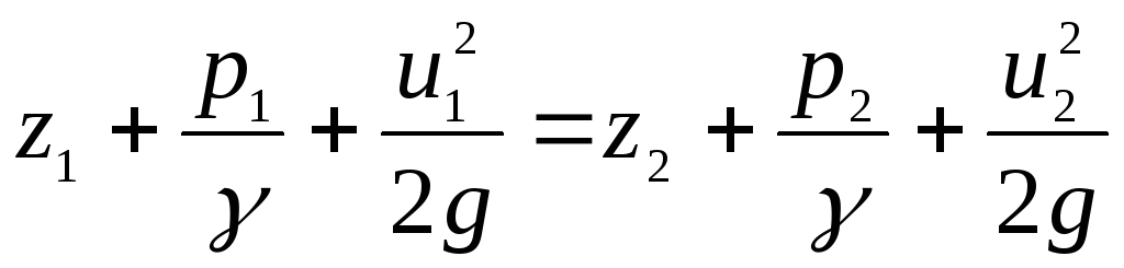
Equation (3-59) or (3-60) is called the Bernoulli equation. It was obtained by Daniil Bernoulli in 1738. This equation applies only to an elementary stream of an ideal liquid.
Let's also pay attention to the following:
1) the Bernoulli equation relates the quantities z, p, and;
2) as can be seen from (3-60), in the case of an ideal fluid, the sum of three terms z,, is a constant along the considered trickle;
3) if the indicated constant value for a given trickle is equal to Alt then for the neighboring trickle the sum of the above three terms is equal to A 2 , and in " general case A 1 ≠ A 2 ;
4) knowing for a given trickle constant value BUT, and also knowing for a given cross section of a jet of three quantities ( z, i, p) any two quantities, we can, using the Bernoulli equation, find the third unknown quantity for the considered section of the jet.
Equation (3-60) can also be obtained by integrating Euler's differential equations (see § 3-3) for any system of body forces acting on a fluid and having a potential (see § 9-2). Equation (3-60) refers to a specific streamline (more precisely: to an elementary trickle along a specific streamline). This equation is often called the Bernoulli integral.
More detailed consideration this issue shows that the Bernoulli equation (Bernoulli integral) turns out to be valid both for the irrotational (potential) steady motion and for the vortex steady motion of an ideal fluid, provided, however, that the body forces acting on the fluid have a potential (in particular, gravity, which we had in mind above). When considering the steady vortex motion of an ideal fluid at a speed and included in the Bernoulli equation, it follows understand (so same as in the case of irrotational motion) the speed related to a real vector field reflecting the motion of the fluid under consideration (the decomposition of the motion into its three types, explained in § 3-4, should not be addressed here).
It can also be shown that in the case of: a) without vortex (potential) motion of an ideal fluid and b) body forces acting on the fluid, having a potential, the value BUT, which was discussed above, is the same for all streamlines forming the flow: A 1 \u003d A 2 \u003d A 3 \u003d --- In this case, equation (3-60) turns out to be valid for the entire area occupied by the liquid, and not just for a certain current lines.
Above, the differential equations of motion of an ideal fluid and the equation of the continuity of motion were obtained, which form a closed system of equations. To solve specific engineering problems, it is necessary to be able to find the integrals of these equations.
Before proceeding to the integration of the equations of motion of an ideal fluid, we accept the following additional conditions:
![]()
![]()
![]()
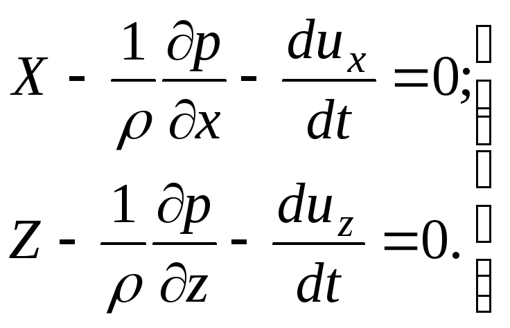
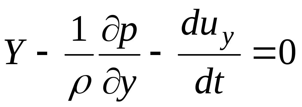
Projections of body force acceleration (in this case gravity) will take on the following values when selected; direction of the coordinate axes:
X=0; Y=0; Z=-g.
After transformation we get:
![]()
![]()
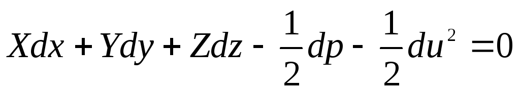
Dividing by g, we get:
![]()
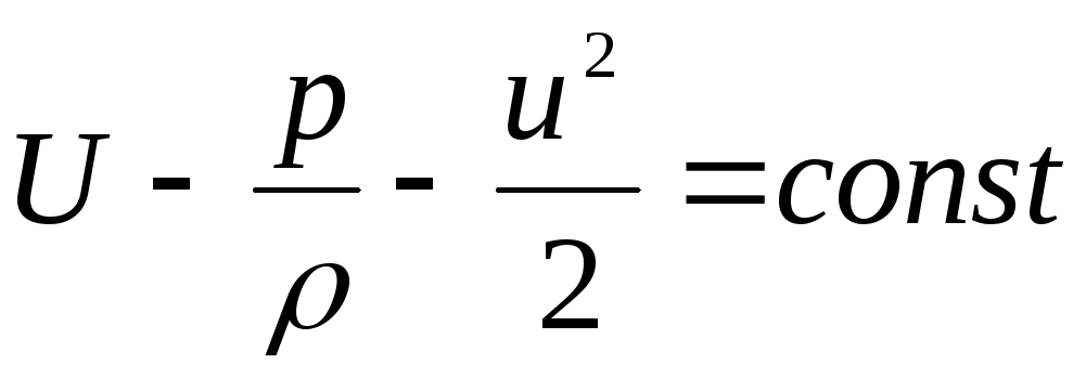
Integrating this differential equation into total differentials, we arrive at the following result:
![]()
This equation is called the D. Bernoulli equation, it is valid for steady motion of an ideal fluid.
For two arbitrary sections of an elementary stream:
![]()
This is the D. Bernoulli equation.
Geometric and energetic meaningequations
D. Bernoulli
All terms included in the D. Bernoulli equation have a linear dimension, so they are usually called heights. Accordingly, the following names for these members are generally accepted:
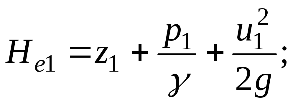
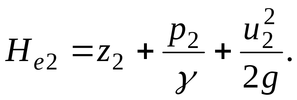
z - geometric or geodetic height;
Piezometric height or pressure height;
- dynamic or velocity head;
It is easy to see the next geometric sense D. Bernoulli's equation, which is that in the steady motion of an ideal fluid, the sum of threeheights (geometric, piezometric and speed) are notvaries along a given elementary stream. This situation is clearly illustrated in Fig. one.
It is possible to interpret the meaning of the individual terms of the equation
Bernoulli is different. It was shown above that the sum
Represents the specific energy of the fluid. Accordingly, we can assume that:
z - is the specific energy of the position;
pressure energy;
There is specific kinetic energy.
The energetic meaning of the Bernoulli equation is that in the steady motion of an ideal fluidthe sum of the specific energies of position, pressure and kinetic does not change along a given elementary jet.

Rice. one
Total specific energy (i.e. potential + kinetic) is called hydrodynamic head and is denoted . Thus, the Bernoulli equation shows that under the steady motion of an ideal fluid for a given stream, the hydrodynamic head is a constant value. On the graph, the hydrodynamic head line is depicted as a horizontal line.
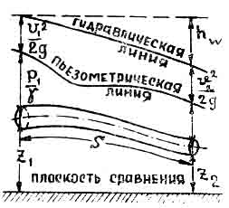
D. Bernoulli's equation for an elementary stream real liquid. Piezometric and hydraulicslopes.
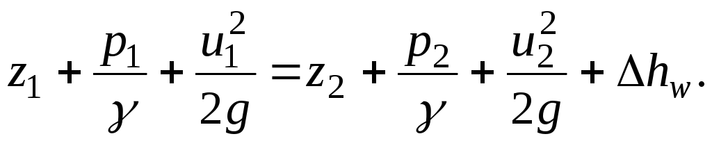
When a real fluid moves between adjacent streams, friction forces arise, to overcome which a part of the energy of the fluid is expended. Therefore, the specific energy of the liquid in the cross section of the elementary jet 2 -2 will be less than the specific energy of the liquid in the cross section 1-1 by some amount , which is called the lost height or the lost specific energy expended on overcoming hydraulic resistance. Analytically, this situation can be written as follows:
![]()
Hence, in the steady motion of a real liquidbone sum of four heights (geometric, piezometricsky, high-speed and lost) or, what is the same, the sumfour specific energies (position, pressure, kinetic and lost) does not change along the given elementary stream.
It is easy to represent the Bernoulli equation for the case under consideration graphically. To do this, after choosing an arbitrary horizontal comparison plane, put on it in each section the height ; ; ; and . The ends of segments z, connected by a smooth curve, will show the position of the axis of the trickle. Connecting the ends of the segments of a smooth curve, we get the so-called piezometric line. Putting in each section up from the piezometric line segments equal to velocity pressures, and connecting their ends with a smooth curve, we get a line of hydrodynamic head or, as it is often called, a hydraulic line (Fig. 2). segments, equal to the distances vertically from the hydraulic line to a horizontal plane passing above the comparison plane at a height equal to the initial specific energy, represent the energy loss for hydraulic resistance in the section from the initial to the considered section.
Rice. 2
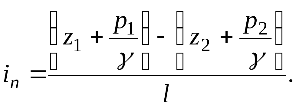
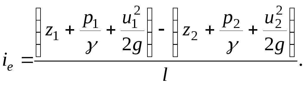
Let us call the fall of the hydraulic line per unit length of the elementary stream hydraulic slopeI:
![]()
The hydraulic slope (Fig. 3) is always a positive value, since the total specific energy of the moving part of the liquid gradually decreases as it moves along the elementary stream, being spent on overcoming friction forces, turning into thermal energy and scattering.

Rice. 3
The concept of smoothly changing (slowly changing) fluid motion
In the general case, with steady motion, the fluid flow can be represented as a set of elementary jets having various meanings angles of their divergence and different radii of curvature. special case dviflow at which it experiences a slight deformationion, so that the elementary filaments remain parallelor almost parallel to each other (), and their radii of curvature are very big values (), called smoothly changing or slowly changing motion.
AT the plane of the free section of the flow with a smoothly changinghydrodynamic pressures are distributed according to the laws of hydrostatics, which means that in a given living section, the specific potential energy of any particle is a constant value:
![]()
D. Bernoulli's equation for the flow of a real fluid.
Conditions for applicability of the equation D. Bernoulli.
Let us extend the Bernoulli equation to the steady flow of a real fluid. To do this, we choose a free section on a weakly deformed section of the flow, near which the motion can be considered smoothly changing.
Through this section, each elementary jet in the time dt energy is introduced, which, in accordance with the above, turns out to be equal to:
Taking out of brackets the weight of the liquid passing through transverse section a trickle per;time dt, equal , rewrite this expression in following form:
![]()
![]()
Rice. 4
Let us find the total energy carried by the fluid flow through the free section 1 - 1. To do this, obviously, it is necessary to sum the resulting expression over all streams of a given free cross section. Then we get:
So the total energy turns out equal to the sum two integrals representing, respectively, the potential and kinetic energy of the flow.
We write the second integral in the following form:

This integral represents, as already mentioned, the kinetic energy carried by the flow through the section 1-1 during the time dt. To calculate it, it is necessary to know how the velocities of fluid particles are distributed over the living section. If we calculate the kinetic energy of the flow under the assumption that these velocities are constant (in other words, according to the average flow velocity in a given living section ), then we get:
This expression is always smaller in magnitude than the actual kinetic energy calculated from actual velocities. Let's denote the ratio of these two quantities:
Since in the flow section between sections 1-1 and 2-2 part of the flow energy is spent on overcoming hydraulic resistance and is irreversibly converted into thermal energy, . It is also obvious that . The difference between these specific energies will express the loss of the specific energy of the flow in the considered section of motion:
After integration and substitution, we get:
![]()
Coefficient is called the coefficient of kineticflow energy and is the ratio of the realkinetic energy of the flow to the kinetic energy, younumerical under the assumption that the velocities at all points of the free section are equal to the average flow velocity. It's obvious that this coefficient is always greater than one.
The resulting equation is the D. Bernoulli equation for a steady flow of a real fluid.
Lecture number 8.
hydraulic resistance.
Classification of hydraulic resistance and pressure loss.
When a real fluid moves, part of the flow energy is spent on overcoming hydraulic resistances, which are divided into two types:
1) resistance along the length of the flow;
2) local resistance.
Resistances along the length of the flow are such resistances that are caused by friction forces and depend on the length of the flow.
Local resistances are those that are caused by a change in the direction or magnitude of the velocity in different sections of the flow. These resistances are caused by taps, gate valves, valves on pipes, sudden expansion or contraction of the flow, etc.
Part of the flow energy that is expended to overcome hydraulic resistance is called head loss or energy loss.
Pressure losses are also divided into two types:
1) head loss along the length of the flow, which are caused by hydraulic resistance along the length of the flow ( h f);
2) local pressure losses, which are caused by local hydraulic resistance ( h i). Total losses head:
h ω = . (1)
The head loss essentially depends on the mode of motion of the fluid.
Laminar and turbulent regime s fluid motion.
There are two modes of fluid motion: laminar and turbulent.
In the laminar mode of motion, fluid particles move in separate jets that do not mix with each other. Examples laminar motion are: the movement of groundwater, the movement of liquids with high viscosity through pipelines (fuel oil, oil, etc.), the movement of blood in blood vessels.
In the turbulent mode of motion, individual streams are mixed with each other. Turbulent motion is observed in nature much more often than laminar motion. An example of turbulent movement is the movement of water in rivers, canals, water pipes, etc.
The word "laminar" comes from the Latin word lamina - plate, strip, layer; The word "turbulent" comes from the Latin word turbulentus - erratic.
The existence in nature of two modes of fluid motion was first pointed out by the outstanding Russian scientist professor D. I. Mendeleev in 1880 in his work “On fluid resistance and aeronautics”.
An experimental study of motion modes was carried out by the English scientist O. Reynolds in 1883.
The experience begins with a pipe pass D liquids at low speeds. At the same time paint is supplied from the tank WITH. In this case, the following picture is obtained (Fig. 1b): the tinted stream has the form of a straight horizontal line, while the rest of the mass of the moving liquid remains uncolored. Consequently, in this case, the particles of the tinted stream do not mix with the rest of the liquid, and the mode of motion of the liquid in the pipe D laminar.
With a gradual increase in speed in the pipe D there comes a moment when the tinted stream disappears and the entire moving liquid becomes uniformly colored. This indicates that the particles of the liquid in the flow are mixed, i.e. in the pipe D turbulent regime takes place (Fig. 1c).
![]()
Rice. one
The speed at which one mode of motion changes to another is called critical. There are two critical speeds: the upper critical speed V VK , at which the laminar regime of motion passes into turbulent, and the lower critical velocity V nk - during the reverse transition.
On the basis of an experimental study of the modes of motion, O. Reynolds gave a criterion for establishing one or another mode of motion.
The criterion for determining the mode of fluid motion is the so-called Reynolds number, which is denoted by Re and is given by the formula:
Where V is average speed flow movements;
L is the characteristic geometrical size of the open section of the flow;
is the kinematic coefficient of viscosity.
The Reynolds number corresponding to the upper critical speed is called the upper critical Reynolds number and is denoted Re vk , at this Reynolds number, the laminar flow becomes turbulent.
The Reynolds number corresponding to the lower critical speed is called the lower critical Reynolds number and is denoted Re nk ; at this Reynolds number, the turbulent regime becomes laminar.
For pressure movement in pipelines, the following experiments have been established: numerical values critical Reynolds number:
Re d (nk) = 2000 2320;
Re d (VK) = 10000 13000.
A real fluid has viscosity, and when it moves, resistance to movement arises. Movement resistance is due to the appearance of forces internal friction. When a stream of a real liquid moves, the mechanical energy contained in the stream will decrease along it, since part of it will be spent on overcoming the resistance, .
This energy is expended on some irreversible work, i.e. to the work of friction forces, and it turns into heat, which is dissipated.
The longer the stream, the more energy will be spent to overcome the resistance to movement.
Energy spent on work of friction forces,
- mechanical energy loss streams that turn into heat. Energy losses related to the unit weight of the liquid when it moves along the elementary stream are called hydraulic losses (losses of specific energy)  .
.
Consider a trickle of a real liquid with steady motion (Fig. 3.8).

Rice. 3.8. To the Bernoulli equation for a trickle of a real liquid
The total specific mechanical energy of a real trickle in its living sections 1-1 and 2-2 will be
Losses of specific mechanical energy due to friction in the area of living sections 1-1 and 2-2
![]() (3.45)
(3.45)
Thus, the Bernoulli equation for an elementary stream of a real liquid in the case of steady motion can be represented as
 (3.47)
A characteristic of fluid motion is the concept of piezometric and hydraulic slopes.
On fig. 3.8 shows the curves that characterize the Bernoulli equation. The line passing through the points corresponding to the value of the piezometric height in live sections 1-1 and 2-2 is piezometric line.
Piezometric slope is the change in the hydrostatic head of the liquid along the stream, per unit length. In the section of the stream with a length  between sections 1-1 and 2-2 piezometric slope
 (3.48)
Piezometric slope corresponding to an infinitesimal length  (at
(at  ), - slope at the point:
 (3.49)
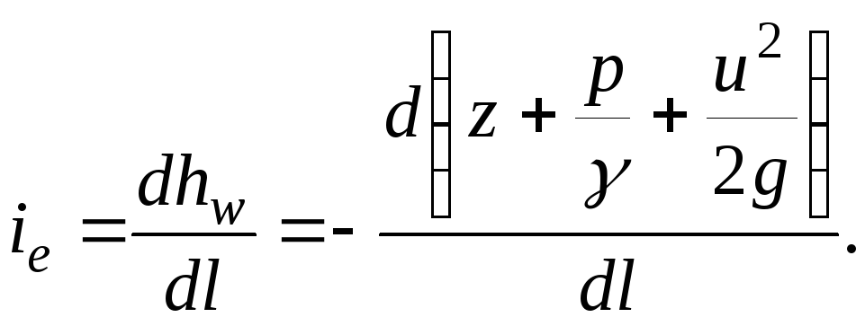
The line passing through the points of values of the specific mechanical energies in the living sections of the filament is pressureline(full pressure line). Hydraulic slope is the decrease in the total specific mechanical energy along the filament per unit length:
 (3.50)
With an elementary decrease in specific energy  on an infinitesimal area hydraulic slope
 (3.51)
Since the total head curve decreases along the length of the trickle, the sign in expression (3.51) minus [  - decreasing function].
In the case of constancy of the living sections along the length of the jet, the piezometric line and the line of total pressure are parallel.
3.9. Differential equations of motion of an ideal fluid (Euler equation)
In a space filled with a moving ideal fluid density  , select an elementary parallelepiped whose edges with sides
  ,
,
 ,
,
 parallel to the coordinate axes (Fig. 3.9). When an ideal fluid moves, there are no internal friction forces. An elementary volume located in a parallelepiped moves with an absolute speed
  . The components of this velocity along the coordinate axes will be
  ,
,
 ,
,
 .
.
Mass and surface forces will act on the elementary volume. The friction forces during the movement of the parallelepiped are equal to zero.
Mass of liquid in the elementary volume of a parallelepiped
 (3.52)
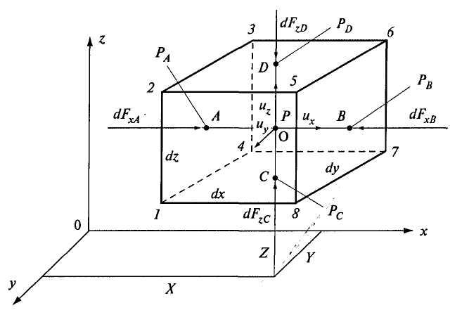
Rice. 3.9. To the derivation of Euler's equation of motion
Projections of mass forces in the direction coordinate axes:
 (3.53)
where  ,
,
 ,
,
 - components of unit body forces with respect to the axes
  ,
,
 ,
,
 (projections of the acceleration of these forces).
Surface forces are determined by the pressure on the faces of the parallelepiped.
Let the hydrostatic pressure at the center of gravity of the parallelepiped (point O) be  , the coordinates of this point ,
,
.Movement speed at this point . The components of this velocity along the coordinate axes are ,
,
.
, the coordinates of this point ,
,
.Movement speed at this point . The components of this velocity along the coordinate axes are ,
,
.
Let's draw through t. About a horizontal line parallel to the axis . Points of intersection with the faces of the box A (face 1234), B (face 5678). The pressure at these points along the axis  and
and  .
.
In a liquid continuous medium, the pressure at a point is expressed by a continuous continuous function of the coordinates of the location of the point in space:  . Hydrostatic pressure changes continuously linearly, and the pressure increment per unit elementary length -
 -
- -
-
Consequently, the pressures at points A and B will differ by  .
.
We express the pressures at points A and B in the following form:
 (3.54)
Due to the small area of the faces, we can assume that the pressures  and are the average hydrostatic pressures acting on faces 1234 and 5678. Surface pressure forces on these faces along the axis equal to the product of the pressure on the area of the faces:
 (3.55)
Similarly, the surface pressure forces on the faces along the z axis (faces 1478 and 2365):
 (3.56)
You can also define surface forces on a face along the axis .
Consider the equilibrium of a parallelepiped in a moving fluid using d'Alembert's principle.
According to d'Alembert's principle, the equation of motion can be considered as an equilibrium equation if we introduce the forces of inertia. We assume that a parallelepiped with mass  moving at a speed , the components of this speed ,
,
.
moving at a speed , the components of this speed ,
,
.
inertia force  (
( - acceleration).
Projections of the inertia force on the corresponding coordinate axes:
 (3.57)
where  ,
, ,
, - projections of acceleration on the axis ,
,
.
- projections of acceleration on the axis ,
,
.
Let us compose an equilibrium equation for the forces acting on the fluid parallelepiped under consideration, taking into account the inertia force along the axes and :
 (3.58)
Substituting into (3.58) the previously obtained dependences (3.53), (3.55), (3.56) and (3.57), we obtain the following equations

Opening the brackets and dividing the equations obtained above by  , write
 (3.59)
Similarly, you can get the equation for the y-axis:
 (3.60)
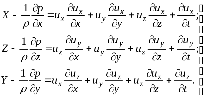
Equations (3.59) and (3.60) can be written as a system of equations:
 (3.61)
In the general case, the quantities ,
,
are a function of the coordinates ,
,
, as well as time  . Therefore, the total speed differential will
Acceleration  ;
;
 (3.64)
Similarly, you can get the speed differentials ,.
After introducing into the system of equations (3.61) the velocity differentials ![]() ,
,
 and
and  she will look
 (3.65)
In case of steady motion
 ;
;
 ;
; . (3.66)
Equations (3.65) are differential equations of motion of an ideal (nonviscous) fluid - Euler's equations. These equations were obtained by Euler in 1775.
The Euler equations express the relationship between the projections of acting forces, velocities, pressure, and fluid density. Euler's equations are very important in the study of fluid motion.
For a fluid at rest, we have
The Euler differential equations take the following form:
![]() (3.67)
(3.67)
The system of differential equations is the equations of fluid equilibrium.
From the equilibrium equation, one can obtain the basic equation of hydrostatics (2.2) (see Appendix).
Integration of Euler's equation of motion. Bernoulli integral
Consider the steady motion of an ideal fluid. We represent the Euler equations in the form (3.61). Multiply the first of the equations by , the second - on and third on , we get
 (3.68)
We add term by term all three equations of the system:
 (3.69)
For steady motion, the pressure  at a point is a function of its coordinates and does not depend on time. Therefore, the pressure differential is expressed in partial derivatives:
 .
.
As  ;
;
 and
and  , then the last term of equation (3.69)
besides
 ;
;
 ;
; .
.
Consequently, the right side of equation (3.69) takes the form
 . (3.71)
Full (absolute) speed and is expressed through  ,
,
 ,
,
 :
:
 .
.
 . (3.72)
Equation (3.69) after transformation can be rewritten in the following form:
 . (3.73)
The first three expressions in this equation is the total differential of the force (potential) function  :
:
Thus, equation (3.74) takes the form
 . (3.75)
Integrating equation (3.75), we obtain
 . (3.76)
This expression is called the Bernoulli-Euler integral.
The resulting trinomial - the equation remains unchanged along the streamline.
In the case when the movement occurs under the action of only one mass force - the force of gravity, then the unit mass forces  ,
, ,
, (axis directed vertically upward). Force function differential
 . (3.77)
Equation (3.75) can be written in the following form:
 . (3.78)
We divide all the terms of the equation by the free fall acceleration  , then we get
 . (3
79)
. (3
79)
The increment of the sum of all three terms of this equation when moving along the streamline is equal to zero.
Integrating the differential equation (3.79), we obtain
 . (3.80)
The sum of all terms along the fluid streamline is a constant value, and, consequently, it is also constant along an ideal elementary stream.
Equation (3.80), obtained using the Euler equation of motion, for steady motion is the Bernoulli equation. An identical equation was obtained earlier in a different way using the kinetic energy theorem (3.43).
Equation (3.80), written for two living sections of a trickle, acquires the previously known form
 .
.
